For more than a decade, THT (through hole technology) became the standard technology in the electronic industry, with a special application in creating reliable and long-lasting board traces. Through the following article, we’re about to expose the basics of the thru-hole, and on top of that, we’ll try to illustrate the pros and cons, common uses, and in particular the SMT relationship of this technology.
What is through-hole technology?
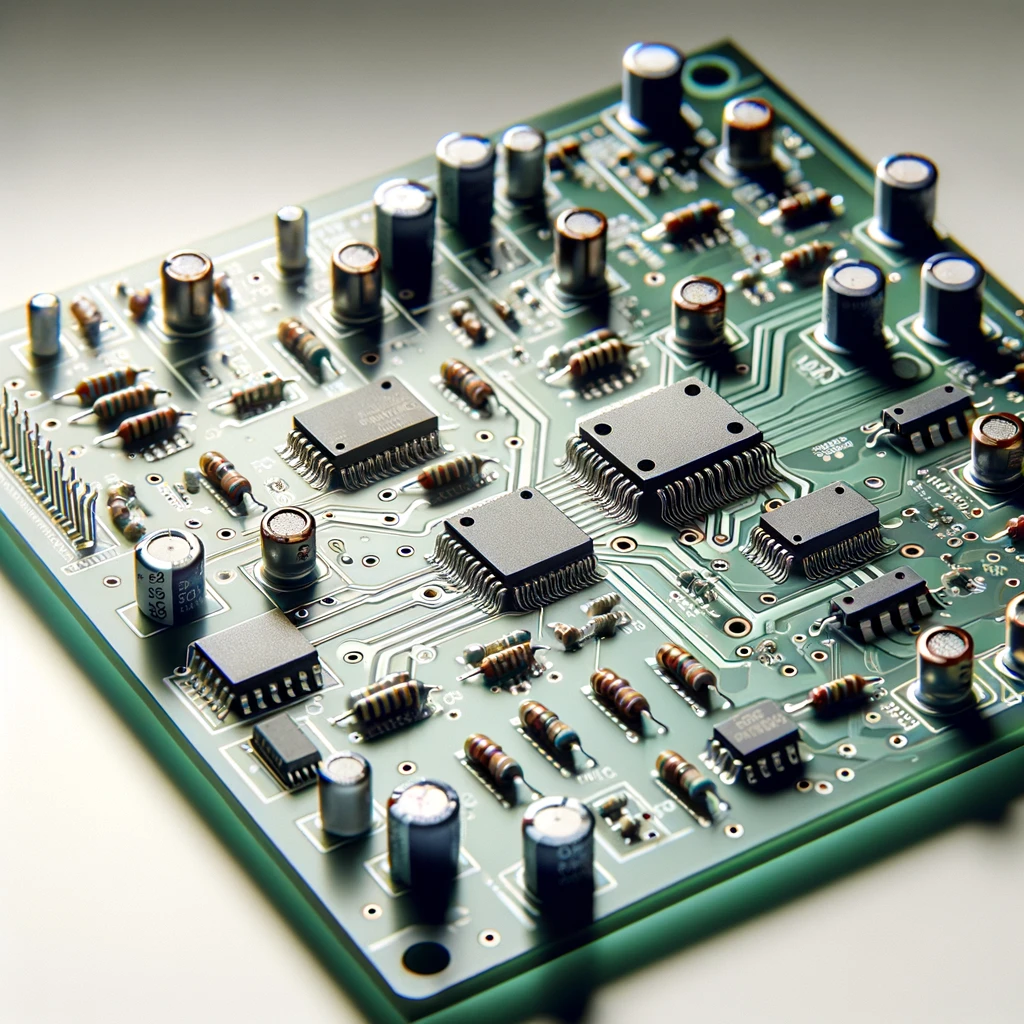
Through Hole Technology (THT) is a form of technique utilized in the electronic assembly process where holes are cored into a printed circuit board (PCB), and components are then mounted by inserting the leads of the devices into those holes. The first step is to use the pick-and-place machine, which is made up of feeders, vision systems, and tracks. Next, the parts are soldered to the opposite side of the printed circuit board (PCB) by a sinner. With such a combination, a device will result.
Components Used in Through-Hole Technology
These are the components used in Through hole assembly
1. Through-Hole Components:
By contrasting with surface mount component populating, the hole method allows parts to be aRPovied or manipulated, which may be used often on a prototype board for the benefit of testing and refining circuitry.
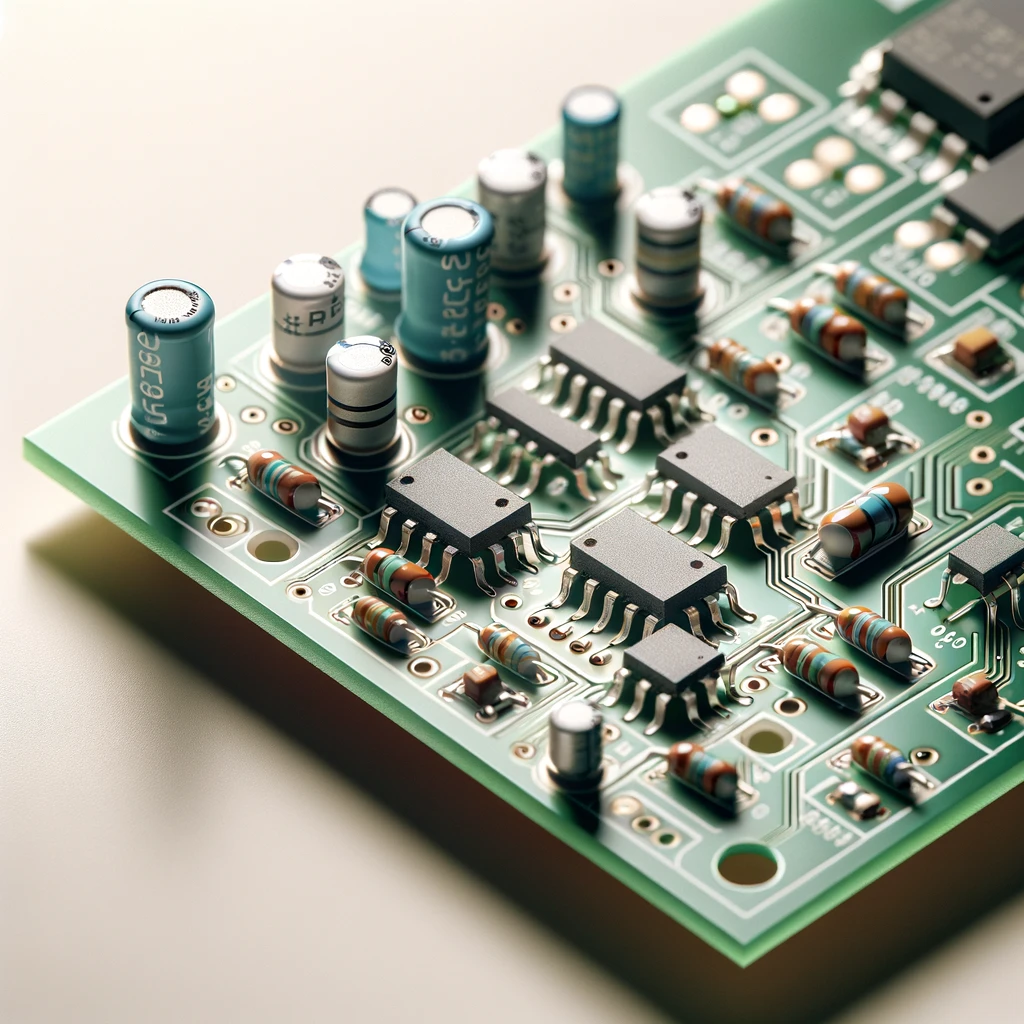
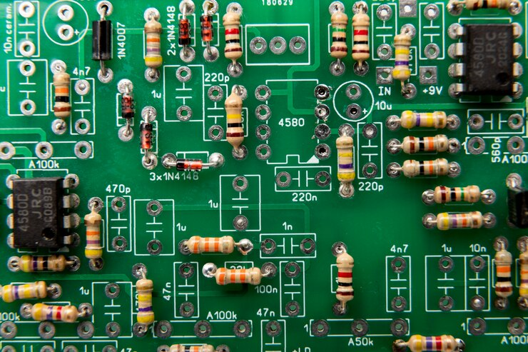
A. Axial Lead Components: These components have axial leads that emerge from both ends of the component body and are bent to fit into holes on the PCB. Examples include resistors, capacitors, and diodes.
Resistors are passive components that limit the flow of electric current in a circuit. They are the parts of the program that regulate the electrical current, so they make it possible to control the current flowing through the circuit. They are used everywhere and are usually used to define the device parameters, such as voltage levels, bias currents, and voltage division.
Diodes are considered semiconductor elements, accepting flows in one direction only. This makes them versatile in the rectification, signal switching, and modulation of electronic circuits. Directly sold/through-hole diodes are often manufactured into glass or plastic holders with two terminal metal ends.
Capacitors store and release electrical energy in the form of an electrostatic field. They are used for filtering, coupling, timing, and energy storage in electronic circuits. Through-hole capacitors come in various shapes and sizes, with two leads for connection.
B. Radial Lead Components: Similar to axial components, but their leads emerge from the sides of the component body. Radial components include electrolytic capacitors and inductors.
Radial Leaded Inductors: Inductors made and produced by the radial through-hole assembly method are characterized by having leads that stick out from their bodies by the side of the hole in the form of a radial pattern.
Radial Leaded Transistors: Now the leads are radial, as that’s the case when the mounted leads go through the holes, which is the typical feature of the older or bigger transistor packages.
2. Printed Circuit Boards (PCBs)
PCBs provide the foundation for through-hole assembly. They consist of layers of non-conductive substrate material (such as fiberglass) with conductive traces that connect the components.
3. Solder

Solder is a combination of various metals that can be used to make connections between components that are not welded and the pathway of the circuit. Although with the increased usage of the ware sourced of the through-hole type, these components are most likely leaded through wave soldering or selective soldering method.
Through-Hole Technology Assembly Processes
These are the Through hole assembly processes
A. PCB Design
1. Schematic Design
The initial manufacturing processes consist of schematic design as designed by engineers. These engineers use the specialized software for the purpose of viewing the circuit in a visual form. The block diagram represents the layout and the location of components. This diagram is like a guide for the actual PCB.
2. PCB Layout
This is when the schematic design will be done. Then, the PCB layout phase will be started. In the next step the components are brought into the position of the board in sequence with the schematic design. Considerations includes elemental size, spacing, and signal routing.
B. Component Leads Placement

1. Manual vs. Automated Placement
Manually, as ones might have noticed in the past, manually components where placed one by one on the printed circuit boards. Nevertheless, owing to the development of technology nowadays, automatic component placement machines of higher level are getting to be more popular as compared to earlier time.
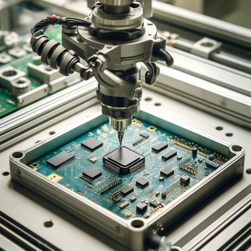
Mechanical machines can position components with great accuracy and speed than manual methods therefore assembly process becomes quicker as compared to manual mechanisms, and erroneous error eliminated.
2. Soldering Techniques
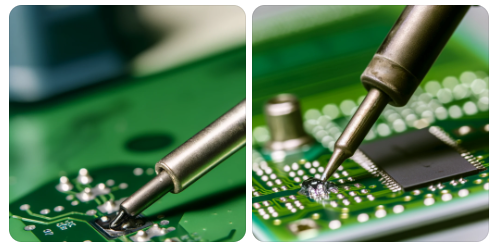
Slightly after the components are put on the PCB, they are soldered to where they were supposed to. Through-holes entail the passage of leads via holes drilled on the original of the PCB, which are then soldered to complete electrical connections. Much common soldering technique includes wave soldering, as well as reflow and molten solder, each of which provide varied benefits in terms of application and production processes.
C. Inspection and Testing

1. Visual Inspection
After soldering, there are visual inspect, and we would detect these problems as solder bridges, place mismatch and soldering mistakes. Sometimes AOI systems (automated optical inspections) which are used for electronic equipment typically have the purposes of visual inspection being highly effective and quick.
2. Electrical Testing
Furthermore, visual inspection is done as a part of assurance process to check if the PCB is properly built. Moreover, electrical testing is also applied to test functionality and integrity of the PCB. This is made by means of performing exams like breakthrough check, functional tests and inside the circuit test (ICT) to find out any electrical faults or performance flickers.
Advantages and Disadvantages Through-Hole Technology
Advantages of THT
Mechanical Strength and Durability: Mechanically, one of the notable advantages of conventional through-hole components is their strength and durability. These elements are usually installed on the PCB by using leads which goes through the holes in the board and provide a connected robust ones which can endure mechanical stresses, vibrations and environmental factors.
Ease of Manual Assembly: Through-hole component assembly are typically bigger than surface mount components which can be advantageous in terms of being easier to handle and assembling manually. This is relevant to instance when mass production is small scale like prototype runs and single units where manual solder and assembly is used.
Improved Thermal and Electrical Performance: Through-hole components offer better thermal and electrical performance in certain scenarios. The larger leads and solder connections provide lower electrical resistance and improved heat dissipation, making them suitable for high-power applications or components that generate significant heat during operation.
Compatibility with Legacy Designs: Many legacy electronic designs and components are based on through-hole technology. This compatibility makes it easier to integrate new components or modules into existing systems without requiring major redesigns or modifications.
Secure Mechanical Mounting: The main benefit of through-hole technology is a secure mechanical mounting method that is particularly well-suited for components that experience additional mechanical stress or require extra support.
Reliable PCB Grounding: The ground wires attached in a through-hole way secure the electrical connection to the ground plane, delivering a decrease in noise, improving signal integrity, and ultimately enhancing the performance of electronic circuits.
Suitability for High-Temperature Applications: Some through-hole components designed to withstand high temperatures enable them to have operations in extreme and severe conditions.
Disadvantages of THT
Size and Weight: One of the primary disadvantages of through-hole components is their larger size compared to their Surface Mount Technology (SMT) counterparts. Surface Mounting devices necessitate the drilled holes in the PCB for the assembly, and as a result, the extra board size and weight are affected.
Manual Assembly Complexity: Contrastily, SMT is predominantly mechanized and is far more automated than THT. However, the THT assembly usually only employs manual adjustments. During the procedure of putting parts through the holes and soldering on backward side of the board, machine time and human power are exhausted.
Higher Costs: The hand labor featured, the use of larger body parts, and the sourcing of components are the main reasons for high manufacturing costs of Through-Hole component in comparison with SMT. This factor implies high expenses, that may be a determinant for organizations with the aim for minimizing the number of operations and expenses.
Exploring the Application and Uses of Through-Hole Technology
1. Automotive Electronics: The automotive industry can serve as an illustration for the wide range of uses of the existing technology of through-hole control modules, sensors, and ignition systems.
2. Industrial Equipment: Industrial machines are generally manufactured using ‘through-the-hole’ technology, which acts as the control panels, power supplies and ports for the modular assembly.
3. Consumer Electronics: While surface mount technology (SMT) has gained popularity in consumer electronics, through-hole technology still plays a vital role. It gains a position of significance in those devices as compared to the rest, where durability and serviceability are the benchmarks, as in audio equipment, power adapters and some displays.
4. Aerospace and Defense: The aerospace and defense sectors utilize through-hole technology for mission-critical systems, including avionics, communication systems, and radar equipment. The reliability of through-hole components makes them a preferred choice in environments where failure is not an option.
5. Medical Devices: These are any devices that are electronically used for the management of equipment, patient management and in diagnostics. Healthcare fields should primarily be focused with aspects such as device durability and lifespan. They should also give far more attention to factors like reliability and accuracy in their practices.
Through Hole Components vs. Surface Mount Components
These are the component:
1. Mounting Method:
Surface Mounted Components (SMC): These mounting components are mounted directly onto the surface mount parts of the printed circuit board (PCB). They do not require holes to be drilled in the board.
Through-Hole Mounting (THC): These components have leads that are inserted into holes drilled into the PCB. The leads are then soldered on the opposite side of the board, providing a mechanical and electrical connection.
2. Size and Form Factor:
SMT Components: Typically smaller and flatter compared to THCs. They are designed for high-density surface-mount packages and are often used in compact electronic devices.
The Components: are generally larger and have a more robust construction due to the space needed for the leads and their insertion into the PCB.
3. Assembly Process:
SMT Components: They are usually assembled using automated pick-and-place machines that precisely position them on the PCB. This process is faster and more suitable for mass production. Surface mount packages have the tendency to get heated to high temperatures during soldering, as through-hole components may not do. So, the components not being rated adequately by considering such temperatures subjected them to mechanical/thermal stress.
THT Components: The entireassembly of THCs involves manual or semi-automated processes. The components are inserted into the board and then soldered, which can be more time-consuming and labor-intensive.
4. Performance and Application:
SMT Components: Offer advantages such as better high-frequency performance, reduced parasitic effects, and improved thermal management. They are commonly used in modern electronics like smartphones, tablets, and computers.
THT Components: are known for their mechanical strength and reliability, making them suitable for applications where ruggedness and durability are important, such as industrial equipment, automotive electronics, and aerospace systems. Through-hole soldering techniques are still used for testing and prototyping.
5. Repair and Maintenance:
SMT Components: They are more challenging to repair or replace individually since they are densely packed and soldered directly to the multilayer boards.
The Components: are easier to replace or repair because they are mounted through holes and can be desoldered and removed more readily.
Common Questions
What are plated through holes?
Through-hole boards became with the plated-through holes (PTH) that correlated to the needed electrical layers. With the help of Surface Mount Technology (SMT) boards, through-hole pads are not needed to make component connections, but they will be made new vias and used as a layer connection.
What are the requirements for through-hole soldering?
Through-hole soldering requires several key elements to ensure successful and reliable connection, such as through-hole assembly component leads, PCB, Solder paste, Flux and Soldering Iron or Station.
In Conclusion
In electronics production, Through-Hole Technology (THT) is an essential element that guarantees dependable connections during PCB design, component placement, soldering, and testing. It is appropriate for demanding applications, including automotive and aerospace, due to its dependability and longevity. Nevertheless, THT encounters difficulties with limited space, which has caused Surface Mount Technology (SMT) to gain popularity for its affordability and space efficiency. Notwithstanding these difficulties, THT is still essential to the electronics sector because of improvements in materials, procedures, and design methods.