Discover the Depths of Through-Hole PCB Assembly with Our Comprehensive Guide: Various expertise, techniques, and best practices for smooth run of the process. Through learning the basics and till now, moving onto complex PCB assembly process, let’s walk the path together towards manufacturing error-free PCBs. Note how to choose essential parts, increase soldering techniques, and fix common problems that might arise. Showing either professional or hobby in your finished product, be a novice or a skilled worker, our guide prepare you for any through-hole assembly project with assuredness and precision.
What is a through hole?
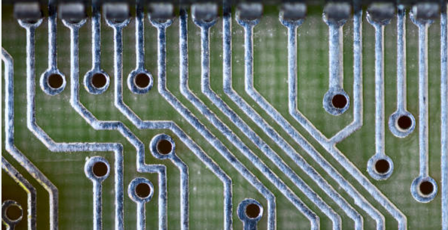
Through-Hole generally refers to a technique of inserting electronic components onto a printed circuit board and using physical leads. The step is related to component placement through the insertion of the leads of components (metal wires) protruding on the bottom of the components into drilled holes through the surface mount assembly PCB. Next, leads are soldered to pads on the opposite side where a drilling holes in the board is done creating an electrical secure connection. The wire-wrapped technology known as through-hole technology was in vogue prior to the surface mount technology (SMT) boards particularly after it became popular. Another case is through-hole parts that still are used not only in many applications today, but also for component leads that need to withstand high power levels or have very convincing mechanical support.
Through-Hole in PCB Assembly
In through hole PCB assembly, the manufacturer attaches through-hole electronic components on the printed circuit board (PCB) using the process of soldering. This method employs component leads that go through a pre-drilled hole on the PCB. The leader or component lead is soldered to a copper pad with a similar hole on its back.
The through-hole assembly process typically includes the following steps:
- Component Placement: Parts can be placed onto the board details using either hand or automatic placement machines as per the design layout.
- Through-Hole Insertion: Holes are drilled on the PCB which then through-hole components by inserting their leads into the corresponding holes of the board.
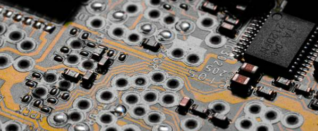
- Soldering: With all the components in place, rather come across as the most important reason why the process known as soldering is carried out. The purpose of soldering is to form electrical connections between the component leads as well as the copper pads on the PCB. Inspection: Finally, the PCB goes for looks and screening to confirm that none of the components have been misaligned, improper soldering or other associated faults.
- Cleaning: Based on the assembly process selected, PCB could be leaderless and any flux deposits or other contamination from the soldering process may be highlighted.
Thru-hole assembly is a quite popular approach when assembling components with the mechanical strength requirement, maximum current carrying capacity, and/or heat dissipation. The SMT is being more commonly used in electronic manufacturing because of its denseness and small size while also being able to hold more components as compared to the through-hole assembly.
Advantages of Through-Hole PCB Assembly
- Mechanical Strength: Through-holes’ PCBs have a generally sturdier mechanical connection than surface-mount components do. The pends of the devices are pushed through the holes and soldered on both sides of the PCB apart from giving overall column support.
- High Power and Thermal Dissipation: Leaded components with thicker leads are widely known to be superior in terms of the capability of carrying higher currents and getting rid of more heat as compared to surface mount substrates.
- Ease of Manual Assembly and Repair: Compared to surface-mount materials, through-hole substrates are more considerable and can be easily dealt with by human hand. These characteristics make them the right choice for manual assembly and repair.
- Reliability and Durability: Through-hole soldering joints are comparatively more resistant to mechanical stresses or fatigue due to their nature of having a conductive pathway from top to bottom completely. This improves the consistency and sturdiness of through-hole assemblies, making them appropriate for use in projects where long lasting reliability is vital, like aerospace, automotive, and industrial electronics.
- Compatibility with Leaded Components: Is the entire assembly of which the wired parts are machined with a large variety of leaded components from the ones with the special lead design/configuration or those pin spacings, which are specifically predefined.
- Testing and Troubleshooting: Surface-mount processing is usually simpler regarding testing and troubleshooting opposed with the through-hole capabilities. The positioning of components in through-hole technology facilitates the visual inspection, probing, and testing of each element as well as all the soldering points during service or repair by the manufacturing personnel.
Limitations of Through-Hole PCB Assembly
- Size and Weight: Through-hole components are generally larger, and hence heavier relative to surface-mount materials. The density of electronic components on the PCB assembly will be higher in this case, which will eventually yield in heavier and bulkier PCB assembly.
- Limited Component Availability: With the growing popularity of the surface-mount technology among small scale manufacturers, ordinary components with through-hole construction are likely to run scarcer in future.
- Reduced PCB Real Estate: Through-hole components often have leads shrouded in solder to be placed into the rock drilled coplanar PCB layers, thus, consuming critical PCB board real estate.
- Manual Assembly Complexity: The through-hole technology can be executed by a manual soldering procedure but it is more lengthy and hard effort comparing with the surface mount procedure when it comes to practical considerations.
- Limited High-Frequency Performance: By through hole boards, the components may exhibit a higher parasitic capacitance and inductance, and thus the performance would seem to be marginal at high frequencies.
- Reduced Thermal Performance: In such case where heat dissipation is the main focus like in the through-hole components which have inferior thermal conductivity than the surface mount components where heat is mostly dissipated from the surface of the component, there is a chance of inferior heat transfer.
- Obsolete Technology: With passing years and advancing technology, surface-mount technology might become the norm in some application areas, rendering the through-hole assembly superseded or obsolete.
Through Hole Mounting Applications
The through-hole mounting option is stunningly popular in many electronics projects as it exploits its specific features which are in many ways useful in particular cases. Here are some common applications of larger through hole is:
- Automotive Electronics: To be operational in an auto electronics setting, some components have to bear high temperature, stress and deterioration consequences of the environment.
- Industrial Equipment: Industrial apparatus, as a rule, is power-driven, operates in rough conditions and is subject to vibration and temperature variations.
- Aerospace and Defense: Components of aerospace and defense electronics are expected to be very robust in order to perform reliably in severe conditions such as exposure to temperatures from the other range, radiation and high level of tension and vibration.
- Prototyping and Development: When designing electronic products, through-hole components that are easier to assemble, solder, and test are mostly used in prototyping and development cycles. Through hole assembly method, designers may get the opportunity of rapid prototyping while these can be tested and even iterated upon with no need of unique equipment and ways.
- High-Power Electronics: Through-hole components are perfect for the applications of high-power where the prototype prototype must have dissipation of heat and the connection of robust electrical is at its peak.
- Legacy Equipment Maintenance: Nowadays a lot of the electronic technology relies on through-hole technology, which means that an older device is not that easy to get rid of completely.
- Educational and Hobbyist Projects: Through-hole parts are considered entry level and are versatile enough for use in classroom settings, hobbyist projects and are also easy to solder.
PCB Layout Considerations When Designing With Through-Hole Parts
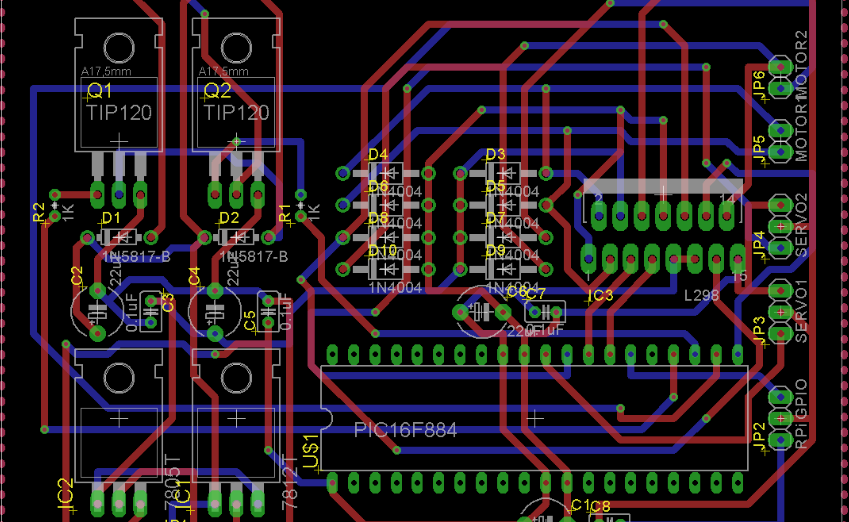
When designing a PCB layout with both through hole component through-hole parts, these factors should be kept into account while the PCB design process is considered. This makes it profitable for the designers to perform selection of layouts that best suit for plated through holes as final products meet the performance, reliability as well as manufacturability.
- Component Placement: Placement of through-hole components on the PCB requires to consider them carefully so as to enable the throguh-signal integrity, thermal management and board assembly and testing for the components.
- Keepout Zones and Clearances: Make up the clearance and keepout areas for the through-hole components to allow their free circulation without any interference such as with other components, traces, and mechanical features on the PCB.
- Trace Routing: The trace path is optimized to reduce non-linear effects such as mismatched impedance, voltage reflections, and cable distortion. Larger traces should be used along high-current lines, and signal traces should be away from noisy and high-powered components for less interference Stick to the same solder wipe widths and go away with sharp bends or corners to ensure good soldering and to avoid signal reflections.
- Thermal Management: When we talk about through-hole components thermal needs, specifically those with prevalent heat dissipating like power resistors or voltage regulators, this is what comes first to mind.
- Mechanical Stability: Take the necessary measures to have a robust PCB backplane, resisting mechanical stress for pins and vibration. Use extra locking holes, reinforcements, or support structure to increase the mechanical strength and dependability of the machine ensemble.
- Solder Mask and Silkscreen: Be sure to include solder mask openings and silkscreened markings to reflect the pad add holes and component outlines in units for accurate placement of through-hole parts and easy checks, and repairs if required.
- Testability and Accessibility: Design the PCB layout accordingly for easier check as well as removal of through-hole components during the manufacturing and assembling phase. You can improve access to test probes or connectors by cutting notches where tear drop marks are located, clearly label components on silkscreen, and leave sufficient space for contact with leads of just casually soldered components or pads of through holes.
- Electromagnetic Compatibility (EMC): Provide for EMC compliance and systematically layout a PCB to reduce EMI disruptions and susceptibility. Lift shielding, ground stands, and utilize effective grounding techniques and where required EMC standards and regulations are to be followed to mitigate the effect of EMI.
Through-Hole Technology vs. Surface Mount Technology
Through hole technology (THT) and surface mount technology (SMT) are the two significant techniques of electronics components assembly to the PCBs, each of which brings advantages and constraints with them.
Through-Hole Technology (THT):
- Mechanical Strength: Through-hole parts have the conductive leads passing through holes drilled into the PCB board and then soldered on both sides of the board, creating a mechanical component connections that is more steady and resilient.
- Heat Dissipation: This means THT components, especially through their large size and leads, have more advantage in heat transferring, which makes them a candidate for high-power components.
- Ease of Assembly and Repair: The ultimate assembly using through-hole technique can be executed in various ways: the manual assembling which uses common soldering practices on a larger scale for the sake of prototypes, small batches of items and repairs.
- Component Compatibility: THT components characteristics which allow the options of sizes, shape and leads configurations are high as a result they can produce a wide range of PCB designs and applications.
- Testing and Troubleshooting: Through hole assemblies also are easier to test and fix because the components and solder joints are typically a bit larger than SMT parts.
Surface Mount Technology (SMT):
- Size and Weight: Surface components are smaller and lighter than through-hole ones, which makes it easier to utilize high component density and smaller PCBs.
- Higher Frequencies: SMD components are characterized by smaller group of parasitic inductance and capacitance, hence their better RF frequency performance in contrast to TH components.
- Automated Assembly: SMT parts are generally constructed by automated insertion mount machines as well as reflow soldering processes. Relatively, this is faster and automated, which can be achieved with higher throughput and lower cost of labor.
- Cost-Effectiveness: Assembling SMT post is usually more economical for high volume deployment because of higher production efficiency, smaller PCB architectures and reduced material usage in an automated process.
- Obsolete Technology: As SMT is ramping up and get widely spread, some THT parts and equipment may reach the end of their life or would be the hard-to-get, therefore this scenario might bring changes in THT design in the future.
Briefly, through-hole technology has its benefits over surface mount devices in terms of their components reliability for soldering, cooling dissipation, and assembly simple carry out and repair work, while surface mount technology is used if the high-volume production and micro-size of the components are more desirable than leading to cost-effectiveness.
Through Hole Components
Through-hole components refer to electronic components that have leads (durable metal wires) which are intended to go through pre-drilled holes on PCBs. These elements are a common ingredient in the construction of different electronic circuits and they also have many benefits, including the mechanical performance and reliability of the equipment. Here are some common types of through-hole components:
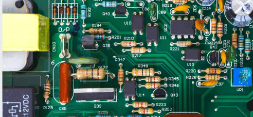
- Resistors: Resistors on surface mount devices works as an impeding agent in a circuit current allowing it to flow easily by offering opposition. This type of components are produced in various resistance values and power output values as well and are often used in voltage drop, current limiting or signal attenuation among other cases.
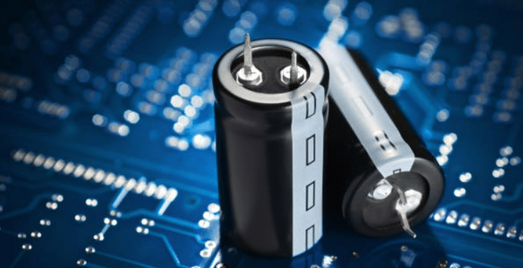
2. Capacitors: Brand-hole capacitors, in through-hole devices, manifest their working principle as a form of an electrostatic field, storing/releasing electrical energy each time in cycles . They are available with different specifications for filtering tasks, decoupling circuits, energy storage purposes and timing features.
3. Diodes: With the use of through-hole diodes, current can pass in one direction by the one direction only, and prevents the current in the reverse direction. They cannot be traded away for their controlling, regulating, conditioning, and safeguarding against over voltage and reverse voltage purposes.
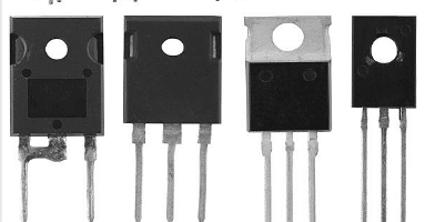
4. Transistors: The through-hole transistor is a semiconductor device that may either amplify or switch on-off electronic signals.
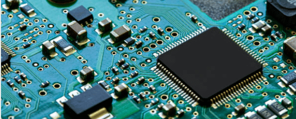
5. Integrated Circuits (ICs): ICs of the through-hole variety comprise a number of electronic components, including transistors, resistors, capacitors, or logic gates, in each package/module.
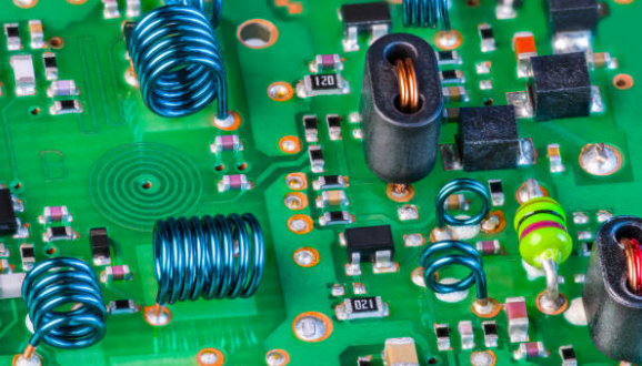
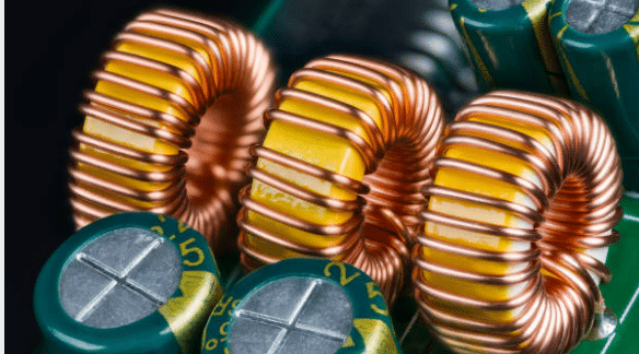
6. Inductors: Through-hole inductors create a magnetic field, as they operate on the principle of induction, they are used in filtering, energy storage, impedance matching, and signal processing for electronic circuitry.
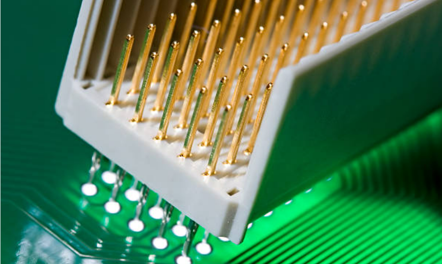
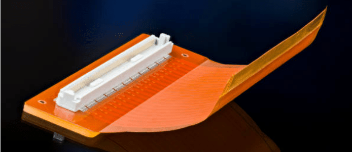
7. Connectors: The thru-hole connectors offer both mechanical and electrical bonding between the PCB and external devices or other printed circuit boards (PCB). It consist different kinds as header, sockets, terminal block and pin header which interfacing cables through and modules or modules and sensors as well peripheral devices.
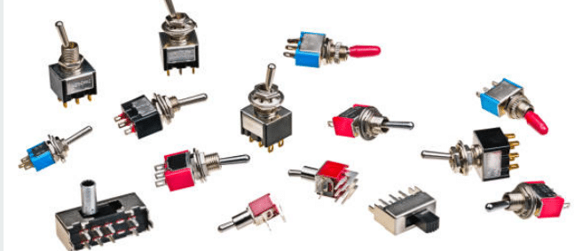
8. Switches: Thru-hole switches configure the flow of electric current through the circuit. The simplest types of switches are on/off kinds or more involved operations that may include rotary switches, linear slide switches, push button switches or depressible DIP switches that are used in selection, control and user interface purposes.
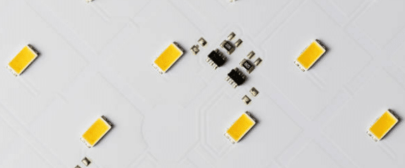
9. LEDs (Light-Emitting Diodes): Through-hole type LEDs will radiate the light when the current goes through them. Such kind of the LED is used as indicators, displays, signs and lighting systems. They have different color shades, intensities, and package styles ranging from T-1 to 5mm LEDs with a through-hole pack.

9. Crystal Oscillators: The crystal oscillators that the through-hole housing technology supports produce precise signals for clock operation to be used in timing and synchronization applications like microcontrollers, microprocessors, communication systems, and digital clocks.
Surface Mount Components
Surface mounting components or surface mount packages (SMT components) are electronic components deliberately designed to be attached onto the surface of a printed circuit board (PCB) against inserting through-hole components like through-hole components (THCs). Through SMT components you can achieve different benefits such as miniature size, high density, and high-frequency performance improvements. Here are some common types of surface mounted components:
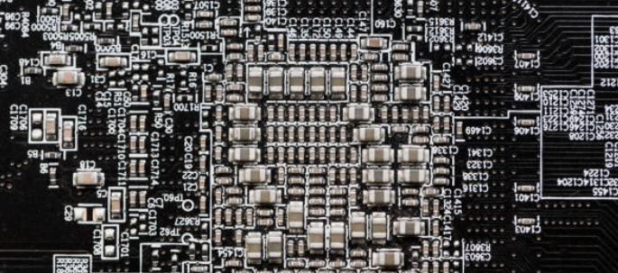
- Surface Mount Resistors: The surface mount resistors limit the current flow in a circuit and come with different values of the resistance and the power ratings. These components are manufactured in various packages with sizes of 0402, 0603, and 0805 and the sizes decreases as the component density increases.
- Surface Mount Capacitors: The surface mount capacitors store and yield electrical energy that can be filtered, decoupled, used for energy storage applications, among others.
- Surface Mount Diodes: In surface mounted diodes current can only move in one direction servings as a barrier to a current flowing backward in the opposite direction. They are applied for conducting dc-dc isolation, control, regulation, correction, and protection of high- or low-voltage conditions.
- Surface Mount Transistors: Surface mount transistors are semiconductor devices, which have amplified or switch electronic signals. Such devices can be in amplifiers, switches, oscillator, voltage regulator and go further with lots of other electronic circuits.
- Surface Mount Integrated Circuits (ICs): These tiny surface mount ICs have more than just one electronic component, i.e., transistors, resistors, capacitors, and logic gates, within the given package.
- Surface Mount Inductors: Throughput difference, this kind of inductors store energy in magnetic field in cases of filtering, energy storage, impedance matching and signal processing in electronic circuits. They are available in different varieties, which include flat wound, ferrite core or multi-layer inductors.
- Surface Mount Connectors: Surface mount connectors are considered physical and electrical connection between the PCB and external devices or the attached boards.
- Surface Mount LEDs (Light-Emitting Diodes): Surface mount LEDs take on the function of brightening when the current passes through them and are refer to the gadgets such as indicators, displays, signage, and lighting.
- Surface Mount Switches: These switches are used on a PCB and perform the function of letting the current flow in and out of the circuit which includes user interface, control, and selection.
- Surface Mount Crystal Oscillators: Surface mount crystals are the devices that are used to generate the exact time clocking frequency range and that are in use in timing and synchronization applications like microcontrollers, microprocessors, communication systems, and digital clocks.
Conclusion
That being said, THT is in essence still one of the major techniques to make surface mount pads and components of electronic manufacturing as SMT becomes the principal technology. The convenience of mechanical connections that are quite robust, simplicity of manual installation and repair, and compatibility with the existing components provide it a favorable condition for usage in the systems that need power handling, durability, and serviceability. As for THT, although its limitations on size, weight and high-frequency performance might be with regard to the SMT technology, still THT is remained to be widely applied in automotive, industrial, aerospace and prototyping applications, which actually demonstrates As these system gradually adopt digital and integrated circuits, there is a need to combine the use of through-hole and surface mount technologies to create robust, efficient, and versatile solutions that can cater to different use cases.