Along with the world’s electronics is moving rapidly so does doing this literally, as we also are doing it metaphorically. Flex PCBs have been the cause of the progress we see in modern electronic devices through their ability to provide flexibility in the design and functionality of modern electronic devices. Each day of our personal or professional lives comes with PCBs wherever we can find it, as it can be found in smartphones and wearable technology or in medical instruments or aerospace components. Flex PCBs provide unmatched versatility and durability. This blog guides through the world of flex PCB design, giving practical tips and methods for you to perfect the designs and make innovative yet efficient solutions.
What is a Flex PCB?
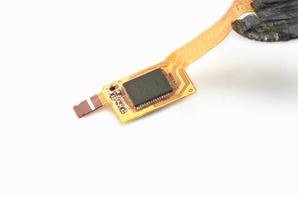
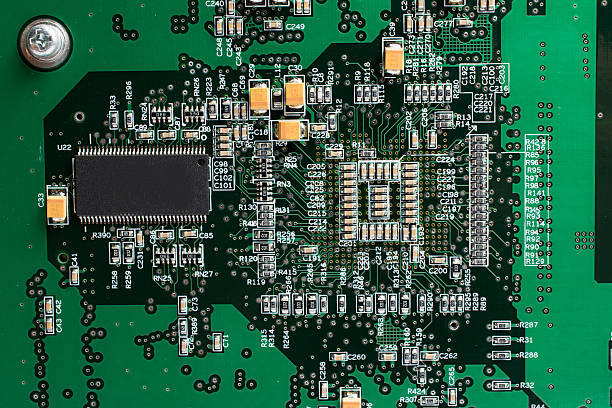
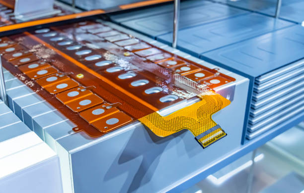
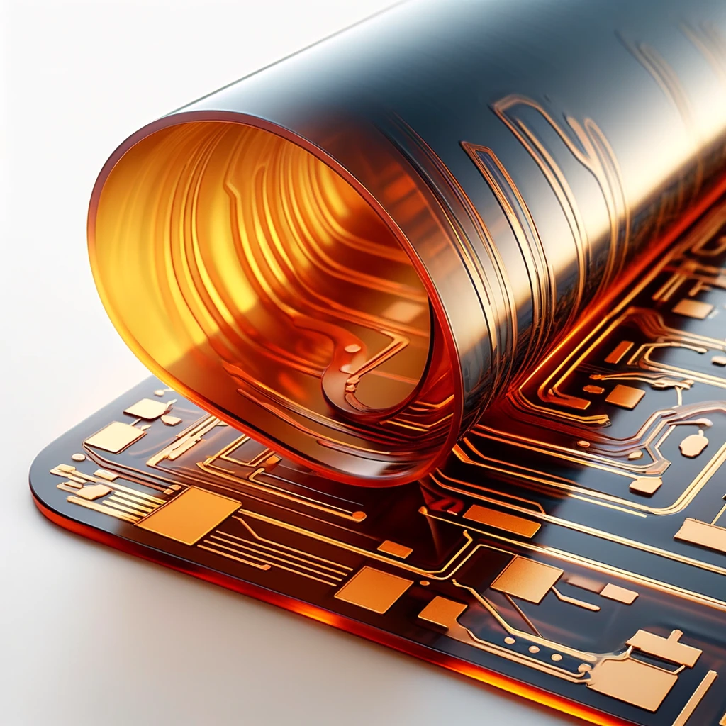
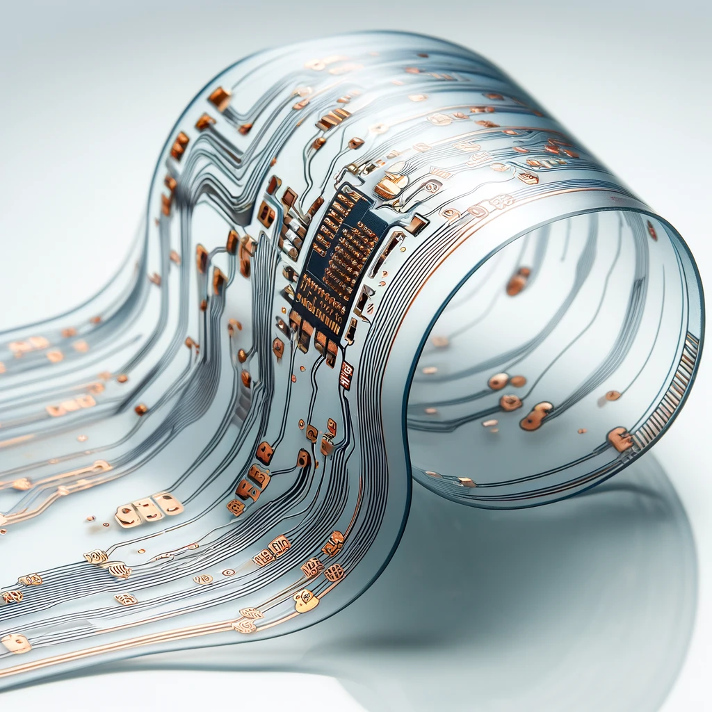
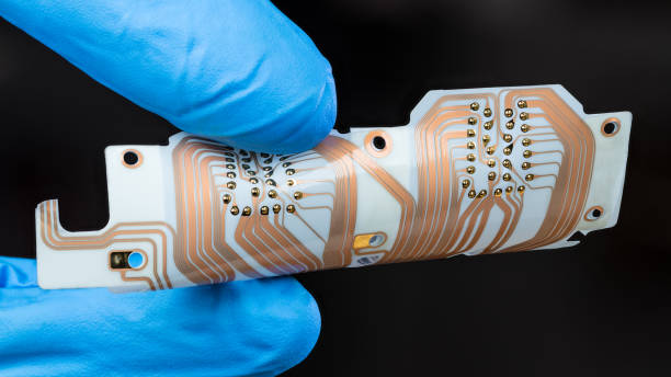
A flexible PCB is a circuit board that is made of a fine material that can bend and twist. It is usually made of a polymer substrate with copper wiring etched or printed. Flex PCBs are much more flexible than usual circuit boards because they can bend and adopt practically any form, thus narrowing the variety of space they can fit into but rigid boards cannot, bringing them into consideration in electronics with limited available space.
Types of Flexible Circuits
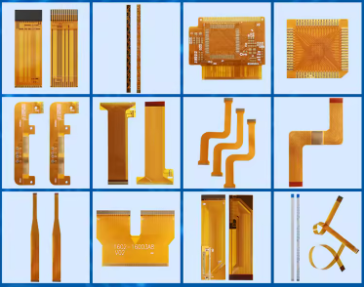
Flexible circuits, or more specifically, flex circuits or flexible printed circuit boards (PCBs), fall under a wide category, with each type designed to address a particular need in the incorporation of electronic devices where space and weight are critical factors. Though there are four-layer flex boards, there are many types of boards with the latest information. The selection of a particular type of elastic circuit depends on the application, its complexity and the requirements of performance. Here are the primary types of flexible circuits:
1. Single-Sided Flex Circuits
These are the most fundamental and sweeping types of flex circuits. The strips’ (mostly copper) conductive layer are laminated on some type of flexible dielectric films. Leadless ICDs have some only one-side features, like being accessed from one side. The single- с machinery fibers circuits usually are applied in the easy cases where a few contacts are enough.
2. Double-Sided Flex Circuits
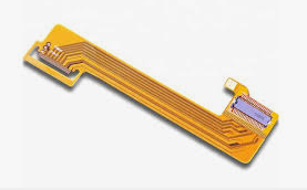
The double-sided flex circuits are composed of two connective modules, an insulator in between them, and plated-through holes through which both sides could be linked. Such an architecture permits high-level arrangement of circuits and produces the required complexity in a very small package. Flex layers with double-sided circuitry can be used where there is some logical complexity in the interconnections, such as those with multiple cross-wiring junctions.
3. Multilayer Flex Circuits
Composed of three or more laminated layers of conductor and dielectric, these circuits are pressed and heated together. PCB layers act as a pathway through which the holes are conducted. Multilayer flex circuits present greater circuit density and are capable of taking care of more complex practices, involving multiple connected circuits, among others.
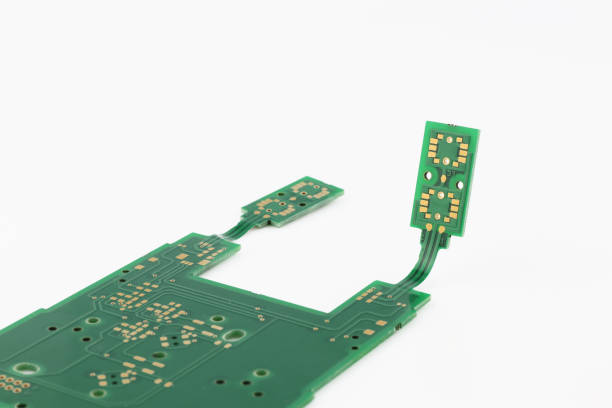
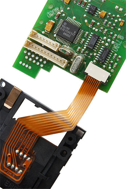
4. Rigid-Flex Circuits

Rigid circuits are made up of flexible and rigid circuit board parts of the individual sleds. The layers that make up these circuits are not as straight as those of rigid flex board. Instead, the layers have an articulate feature that provides a base to mount the parts and as well enough flexibility to bend and fold. This solution is useful for devices that have the same feature, i.e., which require both structural rigidity and which require the circuit to be placed in an unconventional shape or to be moving while in use.
5. Sculptured Flex Circuits
Sculptured flex circuits represent the point where single-sided flex circuits transition into forming a 3D structure at their ends. The term “sculpturing” can be attributed to the formation of conductors’ shapes as they transition from one point to another. This feature provides the connectors with direct integration, which avoids the need for additional components. Write down the main ideas that are presented throughout the text. Conductor lines being formed like a 3D shape in 3D Printing are utilized in applications where a connector is required to fasten mechanical connections without the need for an additional connector.
6. High-Density Interconnect (HDI) Flex Circuits
HDI flex circuits apply a number of the current processes of the industry to optimize the components that are densely packed into a small area. These micro-vias and buried or blind vias are essential features to their designs. With the ever-changing growth of the electronic industry, HDI flex circuits will gradually become the main part of highly reliable electronic products such as advanced smartphones and wearable tech with space, weight and performance on priorities.
This distinctive features of each type of flex circuit and application allow for performance optimization. Of them, there is a choice that depends on the kind of flexion, the accuracy of circuits and the cost constraints.
8 Benefits of Flexible Circuits
Considering that circuit flexibility is also known as flex circuits, it is clear that this type of circuit features a set of advantages that allow it to be used in many electronics that are up-to-date. The one-off properties of these materials are surely a match that no PCB with a rigid flex structure cannot affordably compete with. Here are eight key benefits of using flexible circuits:
- Space Saving: Flex circuits are also compact, which thus enhances their efficiency in terms of space use.
- Lightweight: Therefore, they cut down on the weight of various electronics; hence, portability is enhanced as a result.
- Reliability: Disconnection of fewer connections as well as solder joints reduces the system’s overall reliability as well as its lifespan. It may also result in decreasing the CPU, RAM, and GPU clock frequencies.
- Dynamic Flexibility: The foil components can undergo bending and flexing without fracturing, which is perfect for applications involving movement.
- Design Versatility: Flexible circuits are made in such a way that they can be designed to fit into any shape and style that you want, keeping an eye on functionality and aesthetics.
- Improved Heat Dissipation: In spite of the fact that flex circuits carry unique challenges, they can be engineered to support efficient thermal management.
- Assembly Cost Reduction: Through the integration process, parts are quite simple to assemble, which reduces costs and assembly time as well.
- Environmental Resistance: These treatments enable them to resist harsh environments, which is an advantage for applications in harsh surroundings.
Common Materials in Flexible-Printed Circuit boards
Here’s a concise list of common materials used in flexible printed circuit boards (Flex PCBs):
Polyimide (PI): The most common property of this material is excellent thermal stability and flexibility.
Polyester (PET): high rate of performance and price nest; less temperature resistance compared to polyimide.
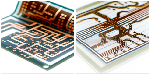
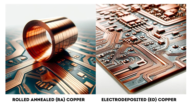
Copper, as the main conductor material, has the best electrical conductivity.
- Rolled Annealed (RA) Copper: It has no limitations in flexibility and is ready to be utilized in dynamic applications instantly.
- Electrodeposited (ED) copper has the ability to withstand stress without a lot of vibration and is used in static applications.
Acrylic Adhesive: Boasts a moderate cost and is strong but not as flexible.
Epoxy Adhesive: high tensile strength and well-resistant to high thermal stress, but not so flexible.
Adhesiveless laminates offer higher endurance and superior thermal properties.
Polyimide Coverlay: Very durable and gives protection against aggressive environmental factors.
Liquid Photo-Imaginable Coverlay (LPI): a decrease in the number of design complexities and the same effects of solder masking.

FR-4 stiffeners give stiffness and some impact resistance and are often used to support sub-assembly.
Polyimide Stiffeners: Features flexibility and sheers at high temperatures.
ENIG (Electroless Nickel Immersion Gold): a corrosion-safe finish; manufacturing component by flat surface.
Immersion Silver or Tin: Simple finishes with good electrical conductivity.
Each material is taken into consideration based on what is required in the specific Flex Layer PCB application, for example, flexibility, environmental resistance, and assembly processes.
Advanced Techniques of Flex circuit
The flex PCB design is a new and trendy method used to achieve complex bendings and loops that can be more difficult with older methods.
Use of Stiffeners
Stiffeners are examples of materials added to some portion of Flex PCB materials to produce a strong support and reduce bending flexibility. They are of particular importance in areas where connectors subjected to loads, high-density components, and contacts need stable support for mounting.
Implementing 3D Design rules
Flex PCBs can be engineered in any 3-dimensional shapes.The eminence of technology contributes vastly in the development of our society, particularly in the field of medicine and health care. With the advancement of scientific techniques and innovations, people have greatly benefited from the use of modern equipments and technologies in the healthcare industry. Whether it is the diagnosis of a patient or assisting in surgical procedures, The possibility of creating such designs by bending the components around the hardware in order to save space enables higher levels of innovation.
Thermal Management
Flex PCBs have bad heat dissipation-compensating properties as compared to rigid PCBs. One essential aspect is thermal management. For instance, generating thermal vias and heat sinks in the thermal management system is essential, especially when handling high-power parts.
Best Practices for Manufacturing and Assembly
These are the technologies applied to manufacturing processes and assembly lines.
- Handling Procedures: Flex PCBs are easily damaged by exposure to workings and storage conditions that do not meet proper handling requirements. Try to use the ends of the boards that are the opposite of the ones that you will see. Apply too much pressure or bend when handling them.
- Assembly Techniques: Soldering at a low temperature will prevent breaking the flexible substrate. However, on top of that, introduce automated assembly processes to minimize the mechanical stress on the PCB during the process of component placement.
Cost Drivers in Flexible Circuits
The cost factors that are present in flexible circuits may lead to a very expensive production of flexible PCBs. Here’s a concise overview of each:
- Material Selection: Materials like high-performance polymide, however, are not only expensive, but the alternatives, such as polyesters, could be potentially cheaper.
- Circuit Complexity: More materials are covered, requiring high precision manufacturing, which increases costs.
- Layer Count: More expensive material and processing procedures support the manufacture of multilayer flex circuits, which are often costlier than single- or double-sided circuits.
- Copper Weight: To allow for greater current capacity without causing a significant increase in production costs, copper layers have to be thick.
- Miniaturization: a Decrease in features and tolerance control necessitate advanced manufacturing technologies, so cost increases.
- Type of Copper: The rolled annealed (RA) copper is more expensive in comparison to the electrodeposited (ED) copper since it has high flexibility and manufacturing costs.
- Finishes: High-quality finishes include ENIG, CLS, and E.C.O. They are more expensive than other types, like immersion silver and tin plating.
- Adhesive Systems: Adhesive wares may be more costly than those made from traditional adhesives, but their reliability and thermal stability grow as a result of this.
- Production Volume: Higher volumes can shift the cost per unit downward, but set-up costs for low volumes can be overwhelming at times.
- Design Revisions: Designs that include many iterations and complex modifications which require changes to be made frequently make development expenses higher.
- Testing and Quality Assurance High-High reliance service testing takes more time, which increases the price.
- Tooling and Setup: Tooling and setup for one-of-a kind designs cost a lot, especially when involving a number of custom-created set-ups.
Grasping of these components are well able to shaped down on selection of right material and processes, while performance needs and budget get balanced in manufacturing of flexible circuits.
Design Tool Issues & Workarounds
Designing flexible circuits poses specific problems that are mostly still not solved in the remains of standard PCB tools, which are normally designed for solid boards. Here are some common issues encountered with design tools when creating flex circuits, along with practical workarounds:
1. Handling of Flex Materials
Issue: The specialized PCB design software that is probably available may not have the properties of flex applications as commonly known, like bending and twisting.
Workaround: Use a software package in which you can display your models in a 3D format or you can make use of these for flexible circuits by only. Features such as the Cadence by Altium or the Cadence are developed with three-dimensional flexible electronics in mind, assisting designers to visualize and try out the designs in three-dimensional space.
2. Complex Stack-ups
Issue: Flex sets could have very dense stack-ups that might not be easy to accomplish in usual PCB design software.
Workaround: Create layer stack-ups in the design software or program the machine using CAD/CAM interfaces. Make sure that the software provides the option for customization of various layer types (e.g., layer type, material, and thickness) while also letting users add different materials with the needed thickness, which is used to correctly model the flex board.
3. Bend Radius Management
Issue: Design tools could be missed the design radius specification, which could be the cause ofthe designs not staying physically when shipped.
Workaround: Work with specifications for bend radii and material properties, and apply them manually. Among instruments of higher design, there is an alertness feature that alerts the designer when the bend radius is too narrow.
4. Dynamic Flexing
Issue: Testing the act of dynamic flexing is beyond the capability of typical PCB design software, which is why it is often not included.
Workaround: In order to accurately reproduce the real-life conditions, utilize this mechanical engineering software together with ANSYS or similar simulation tools that can model the mechanical stresses and strains.
5. Trace Routing Challenges
Issue: Classical with-auto-routing routing instructions might not solve problems of flex circuits-specific, for example, no cross-bend orientation.
Workaround: This process consists in traced routing, mostly when the bends are travelled through in order to make sure the traces are reliable. Utilize a curved trapeze instead of abrupt turns to reduce stress evenly.
6. Component Placement
Issue: Software would not showcase accurate positioning areas for placing components to evade the stress regions. In short, the dependency on software compels the engineers to make extra mental effort to interpret and understand the reliability indicators.
Workaround: Check that components are gently and evenly fitted in the stable domains, away from bend areas. Reinforcement by the structure would be needed for those spots where it is necessary to install parts but where positioning demands rigidity.
7. Manufacturing Constraints
Issue: Most flex applications often depreciate PCB design tools that do not provide manufacturing considerations as opposed to rigid boards encounters.
Workaround: Talk to the producers of manufactured goods and design rules even before the process begins in the software later in order to adjust them manually as they become limited and as they may fail to fit the machine capabilities.
8. Documentation and Output
Issue: Knowing the temperatures applied to different layers and the identification of all bending instructions this step, relaxing things is not effortless.
Workaround: Note-taking and creation of extra documents that go into details of that specific circuit are advisable if the software for designing does not support the making of the specific circuit documentation. Make aspire to good communication with the fabrication house.
Step-by-Step Guide to Designing Flex Circuits
Designing flex circuits entails a laborious process aimed at maintaining flexibility and stability of electronics in devices both of which are vital electrical device qualities. Here’s a concise step-by-step guide:
- Concept and Planning: Discover the application of the circuit and identify the circuit’s specifications such as electromagnetic dynamics, mechanical constraints and ability to accommodate different configurations when needed.
- Material Selection: Select suitable materials for the flex circuit, which may be polyimide or polyester films, among the others, taking factors such as durability under high temperature and flexibility into consideration.
- Circuit Design: CAD software is the next stage, where you will sketch the circuit design. Among design factors warmth bias, space between lines as well as bending radius have to be taken into account to avoid failure of the lines under repeated flexing.
- Stack-up Configuration: Decide on high/low contrast of the layers and their pattern. One facet is of a circuit, which generally includes double-sided and multilayer circuits.
- Component Placement: Distribute components in a wise manner so as to dissipate major stress on the flex area. Make ensure the components are placed on the curved aretas.
- Incorporating Stiffeners: Provide openings for stiffeners at the set location in order to manage the flex surfaces of the components or connectors and reduce stress.
- Design Review and Testing: Ensure the design is stretched to its fullest and every specification perfectly fits into a particular application. Run experiments through virtual simulation tools to get a sense of how the flex circuit would act in the natural world.
- Prototyping: Produce a prototype to test the flexibility and agility of the printed circuit. Consider the significance of testing results when adjusting according to feedback.
- Finalize Design and Production: After the prototype is validated, repeat the design work for production. Take measures of quality control to confirm the acceptance and repeatability.
This guide should provide engineers instructions on how to design flex circuits which are both functional and long lived to meet the requirement of their specific subject.
Conclusion
Mastering Flex PCB design is an art that gives birth to the technical knowledge and ingeniousness necessary to become capable of designing printed semiflexible boards. Through comprehension of the exclusive features that surround the Flex PCBs, engineers can explore further chances in electronics design. All they need is to identify the possibilities and exploit them. You might be working on the smart wearable electronic devices of the next generation or enhancing the reliability of aerospace electronics. In either instance, Flex PCBs are a suitable solution that can help you bring smaller, more efficient devices to the market. Keep in mind that achieving satisfactory rigid and flexible regions, rigid and flex sections, and rigid flex PCB design is, in general, a process consisting of different stages, with the primary one being the planning and satisfying of all the requirements.