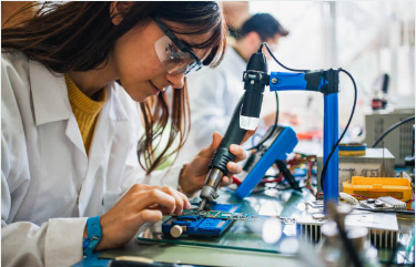
Immerse with us in the outline of soldering in our manual, provided by the top experts, so you will have no problems in high quality PCB assembly. Understand the usual difficulties that come with the job and gain proficiency in best practice while striving for high exactitude in your operations. Take your electronic apparatus experience to the next step with dependable approaches of tinning that give you the confidence that you are working properly.
WHAT IS PCB SOLDERING?
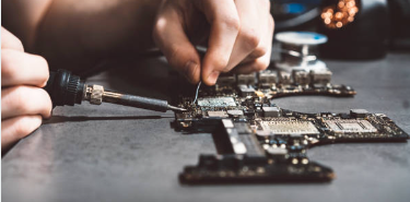
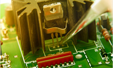
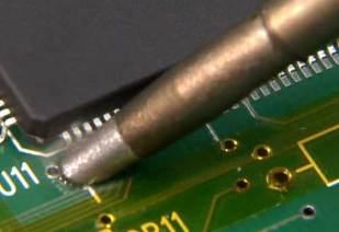
PCB solder process is the mechanism of attaching components such as resistors and capacitors to the printed circuit board (PCB) using solder. During Soldering, conductive components to which they must attach are permanently affixed to the conductive tracks on the PCB, therefore ensuring that the circuit will perform its function correctly. This process consists of heating solder until it melts and using it to the solder pads on the PCB and the component leads. As the solder solidifies, it becomes firm and its bonding effect is stronger, thus ensuring that the circuit is well connected at all ends. We can summarize that correct soldering PCB is critical for the success of electronic devices by the endurance, good performance, and overall functionality.
WHAT ARE THE SOLDERING MATERIALS USED IN PCB SOLDERING
In Soldering PCB, several materials are commonly used:
Solder
Solder is the name of a fusible metal alloy representing a group of materials, mainly electric connectors or wires, which are fastened together using a soldering process. It has a lower melting point than the other metal parts in the space that is being joined and can flow between them when being heated, and turn into a solid that is conductive when heated.
Flux
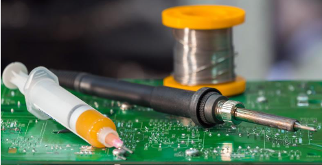
Flux is a Chemical Cleaning agent used to prepare the surface before soldering. It enables the removal of restless elements and contaminants, which is very important, to achieve strong and safe joints. Flux can be a liquid as well as an alloy-solder, or even a paste flux.
Flux Remover
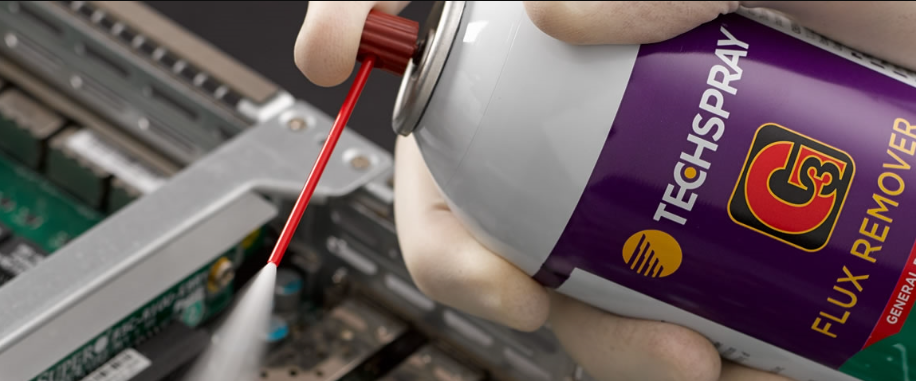
The flux remover is a medium that could be used in chemical form or the solvent which removes the leftover soldering residues. Of all soldering joints, flux is usually applied enough solder first and has a function of improving wetting and flow during soldering, but if burnt flux is not fully cleaned up the residue remains and can be quite corrosive or visibly unattractive.
Flux removers work by dissolving and eliminating these particles excess flux, thus ensuring that solder connections are clean and don’t have any foreign type of materials. They are often employed in the production of electronics and the servicing of electronic devices as the high standards of cleanliness is required for smooth and long-term operation of processing units.
Different solvents exist in different arrangements such as an aerosol spray, a liquid solution, and a wipe that have their solvent absorbed into them. Type of flux required is dependent on the kind of flux used, the product and metals involved as well as the cleaning method preferred by the desired user.
Solder Wick or Desoldering Braid
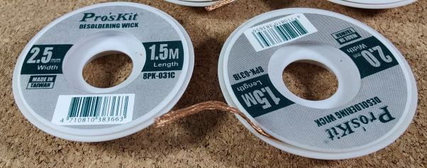
Solder wick or desoldering braid is a braided copper wire to remove the redundant solder from the point of connection surface mount component or the component as you are removing it with desoldering. It is made of very thin copper rods moving next to each other out of the ribbon-like wire shape.
The desoldering procedure normally begins with heating the solder joint with a soldering tool until the solder melts, and then, swiftly withdrawing the solder bridge overheated joints using the solder wick. The solder is then wicked up into the braid by contact with the molten solder using the capillary principle, and it is finally removed away from the joint.
Soldering Iron or Soldering Station
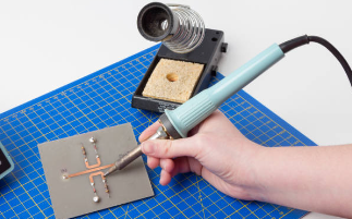
The soldering iron or soldering station should be kept at a distance from children or individuals working with different types of products or documentation.
The soldering gun is the main tool. It makes the solder warm and join them together to make connection. The core part of the soldering tool is a heated metal iron tip that impregnates heat to the solder and the components. Adjustable temperature which ensures a flexible control of the soldering station processes can be found in most soldering stations.
Soldering Flux Pen
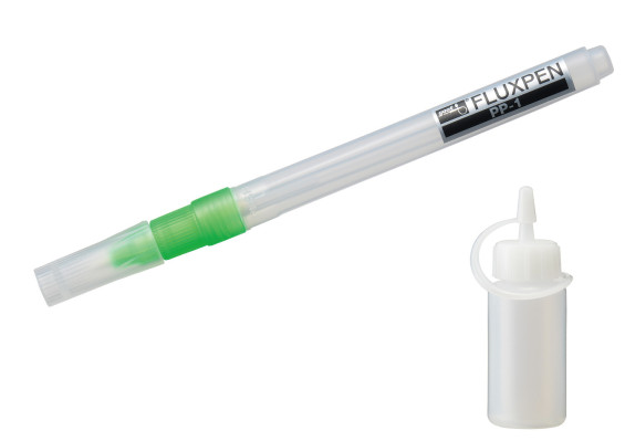
A soldering flux pen is an easy to use device for soldering where flux is applied through the pen as it leaves the solder end of the pen and touches the soldering joint. Flux is a chemical material that is a flux agent or facilitates solderability by removing oxidation from metal surfaces, forming a physical bridge between solid metals and the liquid solder, and enhancing the flow of the two ideal solder joint connections.
Solder Paste
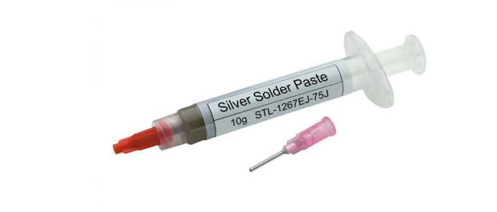
Solder paste, which is made of solder particles and flux and is used in surface mount technology (SMT) for installing electronic components on the copper side of the electronic board (PCB), is an important ingredient. It is the Soldering Process of using force to the solder ball to remove the sections solder wire or “legs” from the multilayer board.
DIFFERENT TYPES OF SOLDERING TECHNIQUES
Several soldering techniques are employed in electronic assembly and repair, each suited to specific applications and requirements:
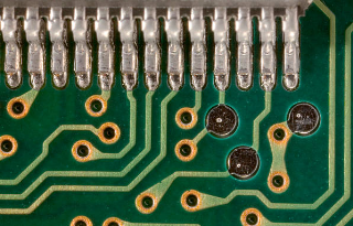
Through-Hole Soldering
It is a classic method where component leads are pushed through holes in a PCB and on soldering on the other side of the PCB using a soldering tool. It is suitable for the soldering of through-hole components and mechanical as well as electrical robustness of joints.
Surface Mount Soldering (SMT)
SMT is the process in which parts are placed and soldered onto the top surface of the printed circuit board (PCB) as opposed to drilling through holes to insert parts. Solder paste dispensers discharge solder paste on pads of a PCB, holes are drilled for the components using pick-and-place machines and parts are soldering pad subsequently inserted into those holes. The solder paste is dried at a certain temperature as the assembly goes to the reflow oven where the solder paste is melted and cold joints are created.
Hand Soldering
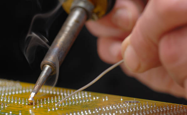
Hand soldering is a manual method by which a pair of hand soldering tool is applied to melt the solder and form the joints between the components and the PCBs. It also has a single unit, which can be used for the whole procedure of soldering, such as through hole and surface mounting.
Reflow Soldering
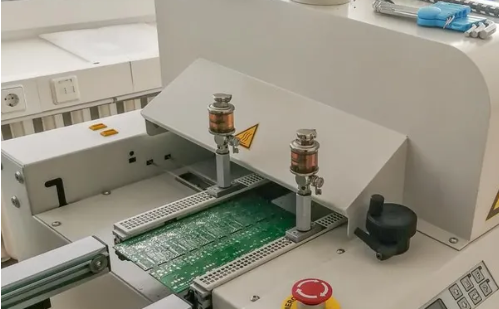
Reflowing solders is the method that is used mostly to solder surface mount components. A stencil with solder paste is pressed to the PCB pads, and area where components needed to be solder sucker placed. Lastly, every part in the platform is shifted to a reflow oven, wherein the solder paste melts, and cold joints are formed. This method is suitable for mass production, and as connections are secured, the method provides uniform and dependable solders.
Drag Soldering
For a soldering tool tip, a small amount of solder is most commonly used in the soldering process called drag soldering. Finally, the hot iron part is dragged all across a number of pins as well as applying solder lead high simultaneously, solder connections being made fast and effectively. It is normally employed to unnecessarily involve makers of fine-pitch surface mounting components.
Selective Soldering
Selective soldering is applied in order to put more solder to a selected area of PCB, with other areas protected from heat damage. This method is commonly used for through-hole components or the areas of the PCB where the solder melting temperatures cannot be achieved. It is also used for the pre-soldering of the areas that cannot be reflowed.
Wave Soldering
Wave soldering is a mass soldering technique of a batch production process with isolation of through-hole components. SMT procession is one of a kind example how the PCB is be passed over a wave of too much heat and solder molten that not only creates solder connections the component leads but also forms solder joints on both component leads as well as the PCB pads. It is also quick and easy, which is advantages in big producing companies.
These Soldering Techniques give the electronics manufacturers and technicians a choice of product, depending on the application needs of the particular hardware or electronic device.
HOW TO ACHIEVE A PERFECTLY SOLDERED CIRCUIT BOARD
Achievement of seamless soldering of PCBs is possible if due care is followed with due diligence and adherence to best practices. Here’s a step-by-step guide to help you achieve flawless soldering tip and results:
- Preparation
- It is vital that your work area is kept clean, well lighted and adequately ventilated.
- Collect all required instruments and components, including the soldering iron, solder, flux, PCB, and the circuit components.
- Component Placement
- Taking great attention put the parts on PCB’ base following the print or the design.
- Verify the direction of movement and ensure the parts are in place to avoid mistakes.
- Surface Preparation
- Scrub the printed circuit board (PCB) and component leads using a PCB cleaner to avoid any contaminants, oxidation, or debris from getting into the assembly.
- Focus on fluxing the pads more so that the solder has better wettability and easily flows to fill the spaces.
- Soldering Technique
- Heat the soldering iron to the level recommended for the solder and components used.
- Make the solder iron tip touch simultaneously both the pins, the lead and the solder pad for symmetrical heating.
- Give a small amount of solder to the joints, and then gently let the solder flow along to create a smooth, shiny fillet.
- Try to avoid any too much solder, as so may result in the formation of solder bridges, cold joints, and insufficient remelts.
- Inspect and Clean
- Look over each solder joint and make sure it is shiny, smooth, and free of any defects with your visual eyes.
- Utilize magnification when required to have close examination of finer pitches of components or small solder joints.
- Remove flux residue using flux cleaner or isopropyl alcohol because this will keep the circuit from being corroded while also making sure that the PCB is clean.
- Testing
- Perform the electrical testing comprising continuity checks or functional test to validate the solder connections integrity.
- Check for faulty component functionality and proof that are no shorts or open circuits.
- Documentation
- Write down any changes or alterations from the original design for future assistance.
- Create and keep record of soldering parameters like temperature and time for being consistent and of course for solving any problem that may come up.
Through the implementation of these steps and by being attentive to detail, soldering PCBs could be performed to the perfection of the finished product with undeniable and lasting soldered connections. Learning how to solder requires regular hands-on contact, patience, and attention to detail that will need to be practiced throughout the process.
THINGS TO CONSIDER TO AVOID SOLDERING PROBLEMS
To ensure successful soldering and avoid common problems, consider the following factors that can minimize common soldering problems and ensure the reliability and performance of electronic assemblies:
- Cleanliness: Make sure to clean the PCB and the parts of the components before soldering by removing dirt, grease, or oxidation as needed. Pollutants may disrupt the solder wetting process and diminish the strength of the solder joint. Contaminants will affect the disturity of the connection.
- Temperature Control: Keep the soldering iron at an acceptable temperature for soldering of proper size and kind of solder. PCBs or components will be damaged by excess heat, while solder starved joint will cause bad joints.
- Solder Quality: Solder with the suitable solder flux should be applied. The right flux core for the application should be used. Low-quality solder can result in weak joints, poor surface overage, and other issues relating to reliability.
- Flux Application: Fluxing and pre-tinning can be applied to the solder joints to better wet this high volume application and remove any remaining oxidation. Low soldering flux might cause solder joint open circuits, whereas solder joints including excessive flux residue can result reliability matters in future.
- Component Placement: Make sure parts are accurately placed and properly aligned on the board before putting them in place. Solder them, make sure they stay in the right place. When two parts are not in perfect alignment or are too loose there is the risk of solder bridges or cold joint or electrical shorts.
- Soldering Technique: Appropriate soldering technique is necessary, including proper handheld and solder application not in excess. Be careful of your soldering practices, because that affects the quality and strength of your solder points.
- Avoidance of Thermal Stress: Eliminate thermal stress on heat sensitive components by joining, use of heat sinks, thermal shields, preheating techniques or other methods. A warming up and cooling down too quickly can lead to different types of component break down or soldering failure.
- Inspection and Testing: Check the solder joint through visual examination and, if possible, using the magnifier to locate any anomalies or imperfections. Carry out electrical calibration, this include continuity checks or functional testing which purpose is to test the continuity of soldering points.
COMMON SOLDERED PCB PROBLEMS AND HOW TO RESOLVE THEM
Solder Bridges
Solder bridges will result if the conductive paths of solder balls or pads are inadvertently connected with the extra quantity of solder material which can cause a short circuit. In order to resolve this issue operate the microscope or the magnifying glass tool effectively for the inspection of PCB for any stray solder or bridges. Following, apply desoldering wick or desoldering pump to remove the extra solder and form a gap in the afflicted pad or trace.
Insufficient Solder Joint
Inadequate joints of solder manifests itself through the presence of less solder that develops poor connection between cleaning pad and the component lead and bridge as well as the lead of solder bridge between the component and the pad of the PCB. One of the methods to handle this is reheating the joint, additionally, the use of just a small amount of solder. Critical to the solder flow is to properly evenly goes around the pad and component lead to make a wholesale connection.
Cold Solder Joints
Most cold solder joint defects are caused due to the fact that the solder on the cold joint regions doesn’t tightly form the connection to the pad or the component lead, this resulting in very feeble contact. Now on to fix this, you have to clean the burnt solder joint with flux and then reheat it by using soldering iron. When the solder flows smoothly and covers the whole of stubborn solder joint, we can get rid of the problem. Do not move the joint when the soldering process is undergoing the cooling risk is exposed to the connection being disturbed.
Lifted Pads or Traces
Surface pads or traces can be lifted from the PCB during soldering which is caused by excessive heat or mechanical stress. To fix it, authenticate the marked-out area very well to establish the degree of the existing damage. If the pad and the trace are still there, you can carefully glue and reconnect them by conductive epoxy or by soldering a jumper wire to connect this lifted pad or trace. In case the damage is appreciable too much solder up, you might have to make an emergency wire jumper to jump the solder bridging damaged segment.
Component Misalignment
Misaligned pins, inappropriate orientation of microchips, soldering errors can come about during soldering as they can result in poor connections, or even short circuits. To solve it, I shift it by the tweezers or a tube pickup or the help of a vacuum pick up. Apply the heating to the old solders and holding the component back in its right place while pushing it gently. Validate alignments of the respective leads of these connectors with both the pin and copper pad materials before the solder begins to solidify.
Overheating Components
Interactive heating may damage parts, especially with ICs, always coined as sensitive components. For this purpose, opt for a soldering iron with temperature control and set it to a temperature that’s comfortable for iron temperature and the components you are working with. Make sure you have the contact with the soldering iron is the shortest possible time to reduce the chance of a overheated joint.
CAN EXCESS SOLDER AFFECT PCB PERFORMANCE?
Excess solder definitely has the potential of greatly affecting the performance of the PCB. Here are some situations or instances in which excess solder can impact PCB performance:
- Short Circuits: The excess of the solder might not just create an essential connection between neighboring solder pads or component leads but also give short circuits, which will have an overall effect on alignment. These issues include a detail malfunction, a component damage, or even the entire circuit stop working.
- Signal Integrity Issues: Inversion of excessive solder can impact the impedance of signal traces to some encumber or the introduction of parasitic capacitance and inductance which could alter signal quality. Doing so may cause signal to be distorted, data corrupted or a communication problem in these circuits. Therefore, these types of circuits require increased attention.
- Mechanical Stress: The thick solder layers can also apply mechanical stress on PCB traces by components (such as solder) in the mentioned situations. This type of stress may cause solder fracture and other types of damages, like the unsoldering of the solder joints, that can reduce the strength and reliability of the PCB.
- Heat Dissipation: If The solder is not maintained, the thermal path between components and heat sinks or thermal pads may be hindered and thus, the heat dispersal performance deteriorated. These can end up with temperature rise, thermal runaway or failure of the units before they are expected to failure like power transistors or the integrated circuits.
- Aesthetic Concerns: Solder fills can affect the cosmetic appearance of a PCB, but they don’t have any direct performance implications. Yes, this may make designing the assembly look too crude or unprofessional, which are not what you want for quality-conscious applications or your end-users.
To get ideal solder joints prevent such problems, it’s essential that we apply the proper quantity of the solder and a good technique. Eliminate solder mask any excesses or bad soldering joints with a solder wick or a desolder tool and then you can visually look at the soldering joints to confirm if they are of high quality. Following the suitable, instruction, and maintaining the frequently to the degree of accuracy are of paramount importance to get the perfect soldering connections on the PCBs.
CONCLUSION
Conclusively, soldered PCBs play great part in modern electronics ensuring durable and reliable electrical connections which are exactly required to guarantee proper device operations and usage. Solder joints lie at the tip of the iron heart of PCB assemblies. From through-hole to surface mount soldering techniques, the perfect and reliable solder joints that provide the basis of any board assembly demands for a cautious approach, appropriate preparation, and the adherences to the best practices. When the use of bad solder joints is uncontrollably high, a number of issues such as short circuits, signia integrity issues, and mechanical strength arise as a result. Through a well observed soldering procedures, maintaining cleanliness and using a proper inspection standards professionals can designate soldering PCB assemblies of different fields of electronic applications dependable, durable and befitting for their function purposes.