Let’s get familiar with the layout of the PCB traces from the design of the past circuit by this rigorous review. The scope of article would be confined to subjects of signal integrity and trace impedance and include a number of routing and controlling techniques. Much the same as how one begins their voyage from the most basic level of fundamental comprehension and moves on to implementing more complex strategy, so does the meta title act as the beginning and end of the journey of the experts, hobbyists, and fans of science. Go through the full details, such as the line width, spacing, and stuff in order to find out if you can affect the calibre and dependability by those details. This guide is tailored both for the beginner and the expert and will lead you through not only the basics but also more advanced levels, so you will eventually enhance your PCB skills and get to know the power hidden by electronics.
What is a PCB Trace?

A printed Circuit Board trace is a conductive individual strip/component of PCB used in the interconnection of resistors, capacitors and other chips or circuit boards. These are commonly known as the copper markings and they are either stamped into the board or, in some cases, printed through the etching process during manufacturing. They are the electric props, the routes that honest signals and power supplies use to follow, bearing the respective link mode. The thickness of the traces, line width, and size of the layers are determined by the purpose of the board and the electronic characteristics defined by the board. Those two factors define the final form of the printed circuit traces.
PCB Trace Width
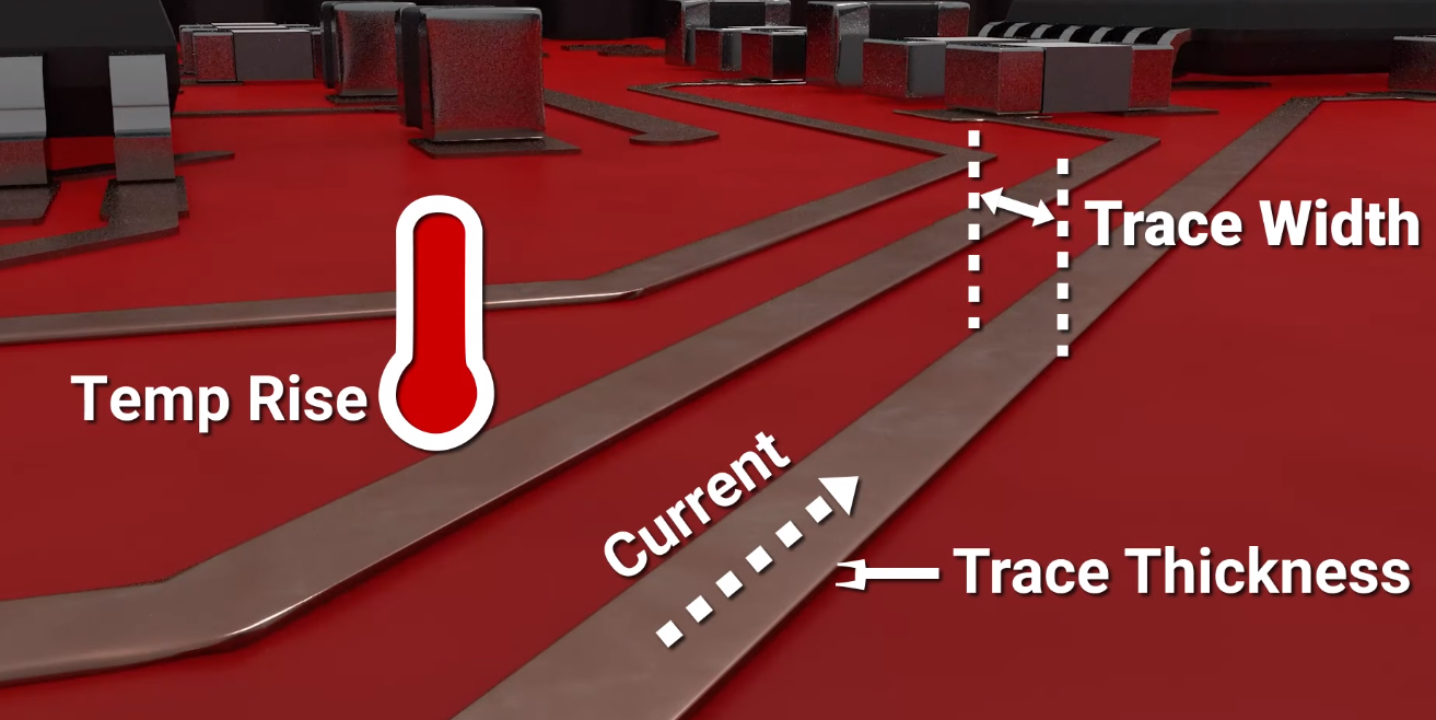
In PCB, trace width PCB designates the shape and size of the element being fed by the current. It is undoubtedly the most crucial key among all of these, as it evaluates the proper trace width and intensity of power without causing the situation of baking or an excessive voltage drop.
The width of the PCB trace, defined in either mills or millimeters by the manufacturer, is capable of withstanding different power demands in a circuit. A millimeter is a small unit of length that is defined as one- thousandth of an of an inchor 0.001 inches. Although a millimeter is a tiny metric unit of length, it can be expressed as one thousandth of a meter (0.001m) or one thousandth of a meter (1mm).
The imperative factor of trace width is the load current, thermal allowable rise and copper thickness of the circuit boards. The suggested design rules and a few algorithms might be the main means to conduct the measurement of PCB trace width, where these factors can surely guaranty certain trace width for the best performance of the PCB under desired operating conditions.
PCB Minimum Trace Width
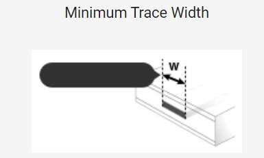
The minimum acceptable trace widths in PCBs is the lowest functionally verified internal trace widths guaranteed to be produced, as has been published by. Position accuracy, along with some other manufacturing techniques, is a critical parameter in order to ensure that the PCB integrates the electrical connections without short circuits or defects of manufacturing.
The decrease in trace length and width, from low to high, might require very precise techniques, and this will depend on copper thickness as well some specific pattern design objectives. At last, I will say that the current PCB manufacturing processes nowadays can shoot for really small trace width proportions.
For instance, in a typical PCB circuit design, the standard minimum trace width is slightly over 0.006 inches or even less than that. On one hand, the latest manufacturing processes, including HDI (High-Density Interconnect), can reach a trace width of 0.003 inches or less, in addition to some of the internal traces also becoming non-conducting.
Designers shall have consultation with PCB manufacturer about effectively determining the minimum trace width permitted by a production method and if it is possible, this trace width would be able to support the demands of the design. Apart from this, sticking to design criteria and looking into details of modern signal carrying capacity and signal integrity can also support optimum trace widths for performance and reliability.
PCB trace thickness

The thickness of the PCB trace denotes the height and width of the circuit pathways that transmit currents from different components concealed on the circuit board through winding patterns. This is of great importance because it deals with electrical issues that are very crucial to the performance of the board.
The thickness of the tracer is indicated either in ounces per square foot (oz/ft2) units or micrometers (µm) units. The thickness of the trace is typically in the range of 0.5 oz/ft2 to 3 oz/ft2 (17.5 µm to 105 µm). However, for specialized applications, we can go thicker.
On the contrary, thinner lines result in a higher resistance level. It is here that the peak flows and temperature rise must be avoided to obtain the best results. By this means, these kinds analog traces of transformers can be used in power lines as well as in high-current applications. For the same reason, the fine traces are used only for signal systems and high-density PCBs, where the busy traces on the internal layers do not even leave any place for them.
Trace thickness will be chosen based on various considerations, including current (A) requirement, signaling, impedance matching, and manufacturing technology. It is generally designed at the chip’s design level, consisting of specialized functional features of the circuits involved.
PCB Trace Resistance
Specific PCB’s resistance of traces depends on its length, width, thickness and base properties. Despite a wire’s longer length, its resistance still go up, which is governed by Ohm’s law (R = ρ * (L/A) as R indicates resistance, ρ refers to resistivity, L is length , and A is equation).
The exact size of each internal layer of the trace, which is A2 in square units, determines the value of the trace cross-section. A smaller resistance is provided by the bigger, wider and thicker traces, as they are able to provide a larger conductive path and therefore a wider area which the current can easily flow through. When traces are made on a Thin Film (TF), their resistance in the cross-sectional area of the thin film is higher than that in the wide trace.
PCB Trace Current
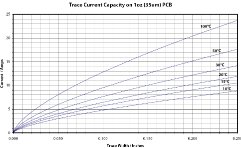
The conductivity capacity of a trace on a PCB is determined by parameters like their width, thickness, material, and temperature. Fatter and carrying thinner traces are able to carry more current since they have low resistance and better heat dissipation. Engineers compute tolerance-dimensions to make sure that it also satisfy these current standards without exceeding the allowed temperature. Either of these could be the solutions employed by them, such as the detailed plan of tapping multiple parallel tracks or increased copper weight for high-current applications. Overall, having enough current capacity is certainly a key factor that defines the device’s dependability and safety.
Computing PCB Trace Width

The process of calculating the width of a PCB trace involves the consideration of factors such as temperature rise limit, the maximum safe current-carrying capacity of the trace, copper layer thickness and the ambient temperature.
Determine Maximum Current
Find the maximum current first, which will pass through the trace; after that,. To give the circuit, it could be the routing of power supply and traces and components that are wired to them.
Find the allowable Rise
Determine the maximum limit of temperature rise for the trace. These TCR values of external traces of the tube are usually prescribed as per the design standards or specific conditions of the usage.
Calculate Trace Resistance
Use the desired value of width (W), thickness (T), and inscribed per unit area resistivity of copper (ρ) to calculate the trace resistance. The resistance formula for a rectangular conductor. The resistance formula for a rectangular conductor is:
𝑅=𝜌×𝐿𝑊×𝑇R=W×Tρ×L
Calculate Power Dissipation
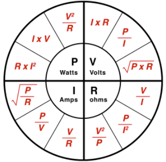
The use of Ohm’s Law (𝑃=𝐼^2×𝑅P=I^2×R) will put more help in the calculations of the given energy of the tap.
Determine Temperature Rise
From heat dissipation to thermal resistance given temperature rise, power to temperature rise, calculate the temperature increase of the trace by leveraging the relationship between power, conduct heat dissipation, thermal resistance, and temperature rise.
Check Against Allowable Temperature Rise
Calculate the calculated temperature rise and compare it with the maximum allowable temperature rise. If it exceeds the limit, change the trace width and repeat calculations until the temperature rise arrives within the allowable range. A hyperlink embedded in the text will automatically lead them to this website, where they can find more information.
Select the Trace trace width.
The bump trace provided the trace rise with temperature coefficient; the allowed temperature rise represented the computed trace width.
When working on a smaller board that requires less copper, there’s a good chance that you’ll use the online calculators or PCB design software that already have built-in parameters for calculating trace widths. This instrument reduces the process by speed, having a higher accuracy currently.
Types of Online PCB Trace Width Calculator
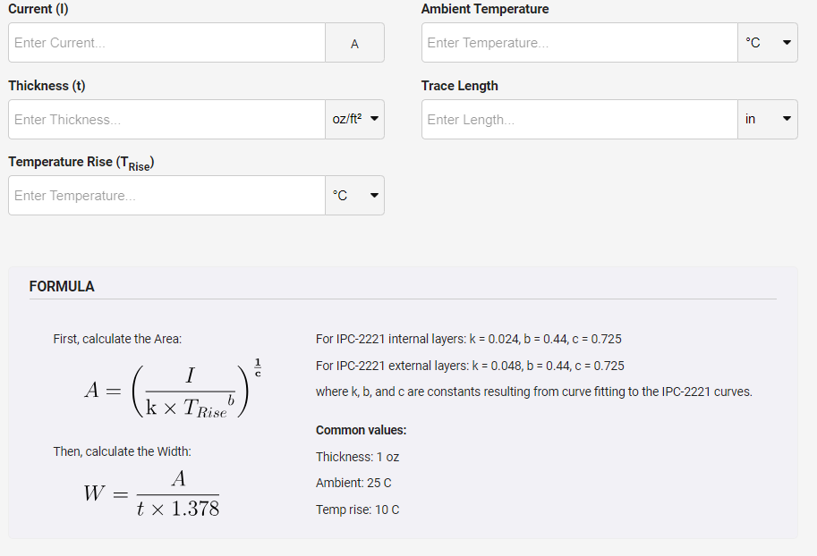
Different classifications of electronic PCB trace width calculators can be found for engineering and design purposes. Here are some common types:
Basic Trace Width Calculator: These calculators take account of a wide range of factors, including the current, temperature rise, copper thickness and material properties, and then indicate the needed copper width. They offer a practical and efficient formula for working out the trace widths of devices with standard PCB components.
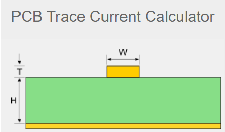
Advanced Trace Width Calculator: Such calculators use more complex-mathematical calculations to determine accurate formulas for trace width. They sometimes take into account other parameters like crawl duration, environmental conditions, and explicit web design standards. Highly efficient calculators afford approximation for sophisticated PCB model through posing more accurate results.
Impedance Control Calculator: When it comes to high-speed digital and RF applications, impedance control becomes something that cannot be overlooked. Such calculators allow trace width and spacing to be found, resulting values in impedance with desired controlled layout routing.
Temperature Rise Calculator: The calculators incorporate the trace temperature rise PCB calculations, which are based on the current variables, trace width, copper thickness, and ambient temperature values. They give room to confidently state that control of the critical temperature remains within permissible tolerance.
Manufacturing Constraints Calculator: Some calculators establish manufacturing constraints like minimum feature size, minimum annular ring, and manufacturability rules for PCB fabrication processes. They assist in verifying the alignment of the calculated trace dimensions with the adopted process to produce trace elements.
3D Trace Width Calculator: These calculators account for the three-dimensional geometry of the outline of a component, including its height and width, and then calculate more exact widths of PCB traces for complex designs.
Embedded Capacitance Calculator: These calculators assist in determining line widths for layouts that incorporate CEM (embedded capacitance material/technique) or similar methods used in manufacture to determine capacitance values.
How do I cut a PCB trace?
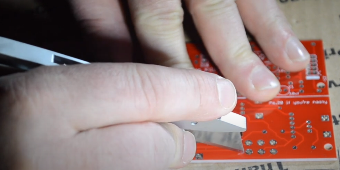
To cut a PCB track, one has to physically break the copper continuity on the printed circuit board. There are several methods to achieve this, depending on the specific requirements and tools available:
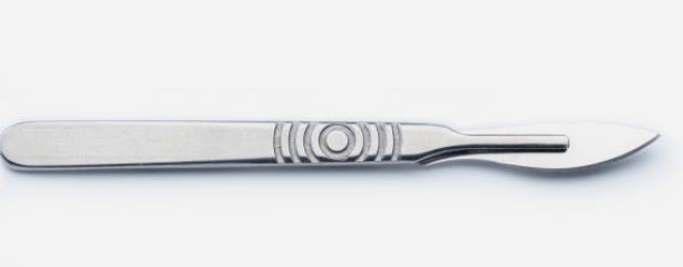
Using a Utility Knife or Razor Blade: Lead the trace line away with a sharp blade or utility knife. Make a slight pressure in such a manner that it would cleanly cut the copper. Proceed with caution to avoid inflicting harm on the parts around you or those on the same level as you.
Using a Dremel Tool with Cutting Disc: A rotary instrument with one twisting device is a disc-cutting Dremel and can be used to cut PCB traces. Willingly squeeze through the trace line using the cutting disc, making sure to be careful and precise. Keep away from other parts of the PCB to avoid damaging them.

Using a PCB Cutter or Guillotine Cutter: There are PCB cutters or guillotine cutters, respectively, which are designed for neat PCB cutting and traces. These tools have been customized for circuit board design and can accurately apply appropriate values onto the schematic without exhaustively having to do a lot of calculations or working them out largely by hand.
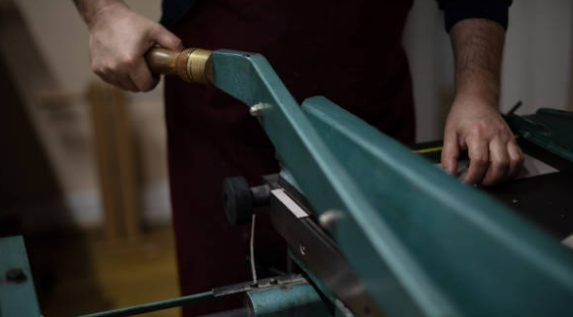
Using a CNC Router: For high-accuracy cutting, a CNC routing (Computer Numerical Control) router is more preferable, as this technology can be programmed to cut PCB traces with even greater accuracy. The technique can be used with production-level PCB manufacturing or prove economical for prototyping
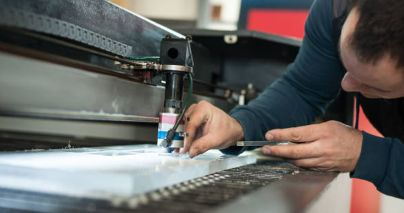
Using a Laser Cutter: Laser cutting represents the third way of getting traces on a PCB that is very precise. Laser cutters create neat line cuts with minimal melted layers on the sidewalls, which makes them ideal for circuit boards. Furthermore, laser cutting requires expensive equipment and safe measures.
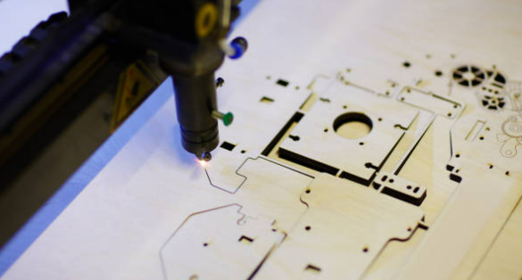
Using PCB Design Software: In some cases, when the PCB layout is designed such that this can be done, you may be able to modify the arrangement in the PCB design software digitally to remove or separate this trace. Such a technique serves its purpose for prototyping or even roughing up the design before switching to manufacturing.

Conclusion
On the other hand, PCB circuit traces play a vital role in attaining the quality of the signal and preventing from electromagnetic interference (EMI) and the generation of impedance. It is essential, though, to develop designers who, for example, can identify and address thermal management system problems as well as stress mechanical forces that cause silicon particles to go off and destroy the circuit board structure. Though technology keeps moving forward, it still constantly introduces new breakthroughs, not only in terms of the techniques used for PCB fabrication but also in the selection of the materials. Such innovations make it possible to create more intricate and compact electronic devices. To sum up, perfecting the design and implementation of circuit traces of PC boards constitutes the cardinal point of work of engineers who strive to create innovative electronics in accordance with present-day trends.

