The Top PCB Design Software for Beginners

The article Top PCB Design Software for Beginners is a brief discussion about basic PCB design instruments which a newcomer to electronics may find applicable. Choice of right software is the key highlighted here stresses that choice of right software is important to reduce the obstacles in learning and achieve better designs. The article focuses on major aspects like libraries, interfaces, working mode, symbolic capture and editor, board graphics, DRC and ERC, and analog and digital simulation. It covers the best PCB design software which includes Altium Designer, Autodesk Eagle, Altium Circuit Maker, EasyEDA, KiCad EDA, Proteus, software of Mentor Graphics PADS, DipTrace, DesignSpark PCB, and OrCAD. In particular, the web page identifies factors such as usability, available tools and libraries, compatibility, and capacity as key aspects relative to newcomers in PCB design software selection.
Step-by-Step: The Turnkey PCB Assembly Process Explained
The article “Step-by-Step: In the article titled “A Comprehensive Guide to Turnkey PCB Assembly and Its Benefits”, the services of turnkey assembly are explained as the process in which “A single manufacturer provides all the essential levels of PCB assembly in a single go.” It reiterates a number of benefits of turnkey assembly; time and cost reduction; efficiency; design advantages; and ease of communication within an organization. Some of the crucial activities which are incorporated include designing, selection of components, manufacturing of printed circuit board, assembling the components and soldering, testing and quality control, and last but not the least packaging. The article also differentiates between partial turnkey PCB assembly as well as full turnkey PCB assembly and the industries it finds applicability by this kind of services and products are the consumer electronics, medical devices, automotive, aerospace and defense. By doing so, it also includes factors to consider when selecting the appropriate turnkey PCB service provider.
The Future of Electronics: Exploring the Role of Surface Mount Technology
The article “The Future of Electronics: In “The Significance of the Use of SMT”, the focus is on the importance of Surface Mount Technology (SMT) and its application in today’s electronics manufacturing industry. It states that SMT allows the use of electronic components to be assembled in a mounted position directly on the surface of printed circuit boards (PCBs) as a distinct form of component mounting from that offered by Through-Hole Technology (THT). miniaturization of electronic devices, hierarchical interconnects, more functionality all these objectives and enhancements can only be achieved by SMT. A brief overview of how SMT works and its benefits like consumption of less space, enhanced performance, and lower cost are discussed in the article and certain limitations like reduction in package sizes and heat dissipation are also highlighted. It also covers trends for SMT’s future developments on the material, automation, and the addition of artificial intelligence monitoring. In general, the picture being painted here is one of SMT as a revolutionary technology that is creating and guaranteeing higher efficiency in electronics production.
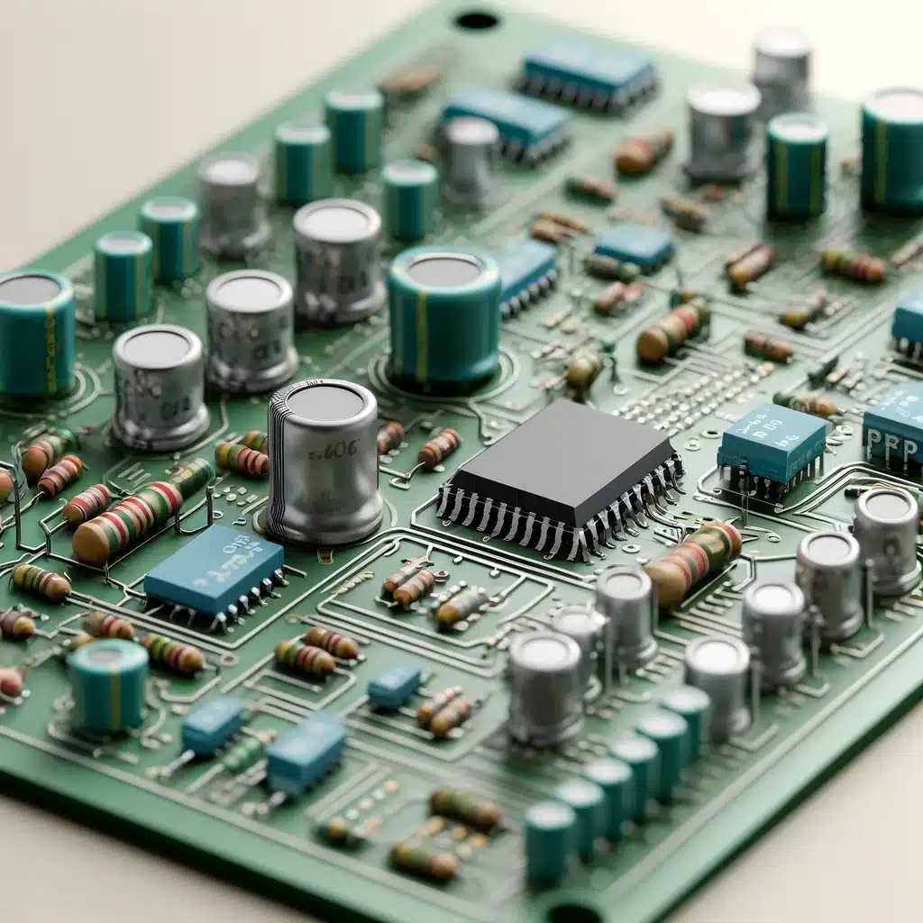
Understanding Through Hole PCB Assembly: A Beginner’s Guide
The article “Understanding Through Hole PCB Assembly: This article titled, “A Beginner’s Guide,” will be defining what Through Hole Technology (THT) is in the context of electronic assembly. THT is described as an approach that involves the use of through hole components which are inserted into round holes on a printed circuit board (PCB). The specific types of axial and radial lead components used are described, as is the process of creating the Printed Circuit Board, or PCB, on which the components will be assembled and the methods by which the components is connected to the PCB using soldering. It also describes advantages of THT as the mechanical strength of the final assembly, ease of manual soldering, and enhancement of thermal and electric conductivity compared to the SMT, at the same time, it defines the disadvantages, like THT brings larger size and higher cost for the circuit board in compare to SMT. The guide focuses on THT’s application in areas that are demanding in terms of circuit reliability and material endurance, for instance, motor vehicle, industrial, and aviation electronics.
The Ultimate Guide to Via Design in PCBs: Everything You Need to Know
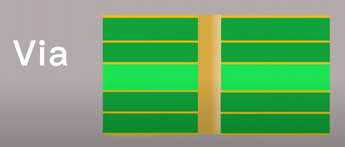
The document “The Ultimate Guide to Via Design in PCBs: The article also serves the purpose of identifying and explaining the different types of vias and their purpose in printed circuit board (PCBs). Vias are known as vertical interconnect accesses and they play an essential role in providing metallic paths in between the layers of a PCB. This guide provides descriptions regarding through-hole, blind, buried, microvias, via-in-pad, filled, and capped vias and where they may be utilized. It also includes the utilization of vias for signal routing, power and ground distribution, component connections power and ground distribution, high speed signal routes, and thermal relief. Further, the guide addresses how to set up the proper via requirements of the PCB projects based on the designs, the manufacturing limitations, and environmental factors required.
Comprehensive Guide in Testing for PCB: Ensuring Quality and Reliability in Circuit Boards
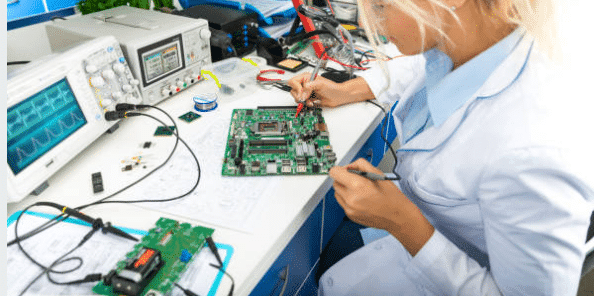
The article “Comprehensive Guide in Testing for PCB: Writing a comprehensive coverage on “Quality and reliability in circuit boards” reviews different techniques used to test printed circuit boards (PCBs). It includes the importance of testing PCB in electronics manufacturing industry and how important it is to conduct a proper test in order to diagnose the shortages, mistakes or any other problem that may hinder the performance or the life expectancy of the printed circuit Board. It outlines the various test methods such as visual image test, manual and automatic optical inspect, X ray inspect, ICT and functional test. The benefits as well as the shortcomings of each of the methods are presented and it is demonstrated that one has to work in compliance with standard and norms if one has to produce high quality PCBs. The article also discusses difficulties inherent in the testing of PCB, including miniaturization of chips, PCB design complexity and environmental testing; and provides remedies through technological and testing approaches.
Demystifying PCB Circuit Traces: Everything You Need to Know
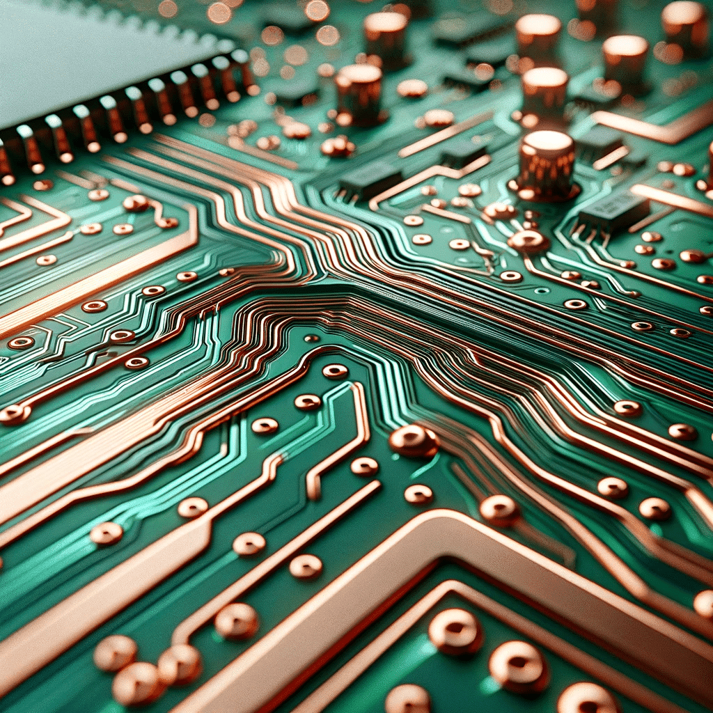
The article “Demystifying PCB Circuit Traces: In the article “Everything You Need to Know” detailed information can be found about the traces of PCB (Printed Circuit Board), these are thin conductive paths that form circuits. It also presents information on signal density, signal speed, and some of the most common routing methodologies deployed on PCB traces. Tap in Imperative aspects such as trace width, thickness and resistance; the article under discussion elucidates their significance leveraging their influence it on the electrical performance and dependability of the PCB. Besides, it describes how the trace width should be determined, the management of high current tracks, and the thermal considerations for maintaining the reliability of the print. As such, this guide is written for both the novice and the advance levels, the ultimate purpose being to improve their comprehension and abilities in regard to creating and market PCBs.
Crafting Effective EMI Design: Strategies for Ensuring Electromagnetic Compatibility
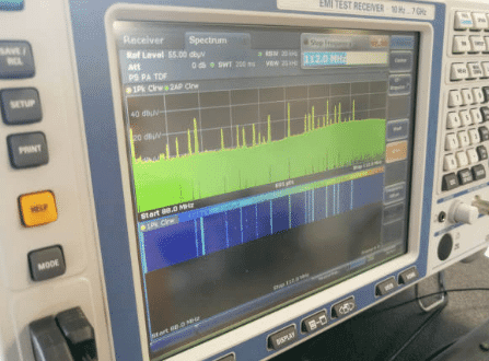
This article aims at introducing the key notions about EMI and share basic and some enhanced techniques for designing for EMC by electronic devices. Thus, this work aimed to cover the following sections: EMI sources, basic types of electromagnetic interferences, and some tips for EMI suppression. Some of recommended procedures include ground, shielding and filtering, this Time complexity and is followed by compliance testing and reference to EMI/EMC guidelines. There is an element of decreasing interference with an aim to enhance performance of the electronic based devices in operation.
The Ultimate Guide to Turnkey PCB Assembly: Everything You Need to Know
Turn-Key PCB Assembly is a convenient and easy solution for making PCBs. It is a one-stop solution in that the supplier will handle everything from component sourcing to final assembly and testing. It is an all-in-one service in the sense that the client can give design features after which they will receive fully assembled and tested PCBs without necessarily coordinating with many vendors. The whole range of Turn-Key PCB services can vary from full turnkey to partial turnkey in which the client gives some components or part assembles PCBs. The most preferred one is Turnkey assembly, which saves time, cuts costs, and reduces risks associated with electronic assembly work. The full turnkey service will help in streamlining project management in a way that it will guarantee high-quality production, which will enable the customer to concentrate on core competencies in the market, thus being able to take customers to market more quickly.
A Comprehensive Guide to Designing Multi-Layer PCBs for Optimal Performance
The document contains a guideline to the design of multi-layer printed circuit boards that will be quite comprehensive in order to attain the desired performance. The document touches on the material selection, layer stacking, routing techniques, testing practices, and the final conclusion of the output thereby, it covers numerous aspects. Multi-layer PCBs are those PCBs which have several conductive trace layers which are separated by the insulating materials and used in devices like computers and smartphones for maintaining signal integrity and for the reduction of electromagnetic interference. The document also highlights the fact that the number of layers should be directly related to the number of the circuit, signal integrity, and cost. The Document also emphasizes the benefits and the uses of multi-layer PCBs to make the performance and the reliability of the electronic systems better.