As the world progressively gets into high-tech electronic products, high-frequency PCB design is one of the most important tasks that requires a clear understanding of what drives its operations. Whether you work in the field of communicating 5G, aircraft equipment, or medical devices, designing high-frequency PCBs (printed circuit boards) that answer your questions for signal quality, impedance control, and reliability is essential. This complete overview will cover the salient points regarding design, tips, and guidelines for high-speed PCBs that have excellent performance.
Understanding High-Frequency PCBs
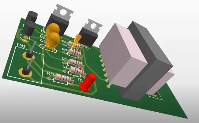
One category of high-frequency PCBs are specialized circuit boards, which are intended to operate signals that have a higher frequency than what conventional PCBs are capable of. They are built with better electrical properties than others so as to reduce signal loss, save the signal, and maintain signal integrity. One of the materials used in designing PCBs is a braided and soldered mask (FR-4 with high Tg). Others are Rogers and Isola, which are specialized laminates.
What is a high-frequency PCB?
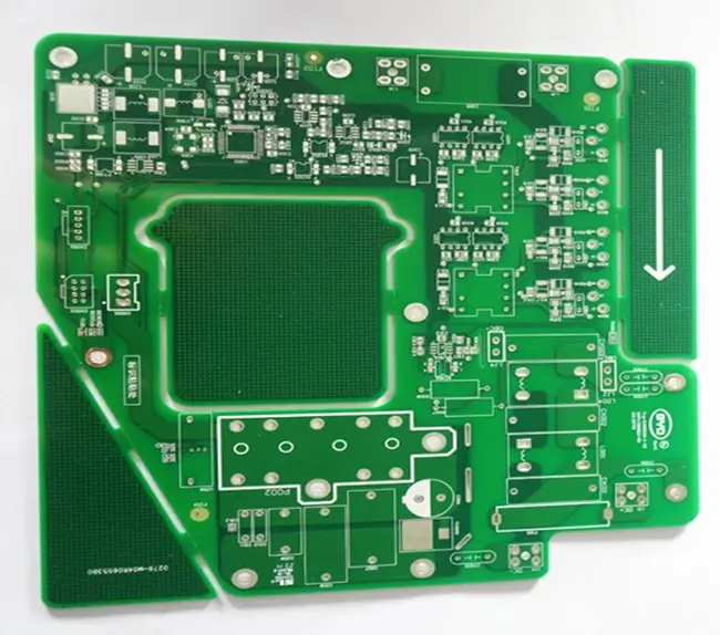
In contrast with the regular PCB, a high-frequency PCB consists of a line board that can transmit high-frequency signals through guides. These boards are composed to be made from material with good electrical performance, i.e., a small dielectric constant or low loss tangent, to prevent or minimize signal loss and have signal integrity. Frequent PCBs are typically utilized in devices that need higher-speed communication, for instance, 5G networks, some aerospace devices, and medical equipment.
What are the characteristics of high-frequency PCBs?
High-speed printed circuit boards (HFPCBs) have a series of unique properties that very much distinguish them from normal flexible PCBs. These characteristics are crucial for ensuring optimal performance in high-speed applications:
| Characteristic | Description |
| Low Dielectric Constant (Dk) | Reduces signal distortion and loss, enabling faster signal propagation. |
| Low Loss Tangent (Df) | Minimizes signal attenuation, ensuring strong and clear signals over long distances |
| Stable Dielectric Constant (Dk) | Maintains a stable dielectric constant over a wide range of frequencies, ensuringconsistent performance. |
| Excellent Thermal Stability | Withstands high temperatures without degrading, ensuring reliability in demandingapplications. |
| Tight Impedance Control | Requires tight tolerance for impedance control to minimize signal reflections andensure signalintegrity. |
| Uniformity and Consistency | Manufactured to strict quality standards for uniformity and consistency in electricaproperties. |
| Compatibility with High-Frequency Signals | Designed to handle high-frequency signals without distortion, ensuring reliable datatransmission. |
- Low Dielectric Constant (Dk): This is why the low-dielectric constant approach is often chosen by PCB engineers as the material for high-frequency PCBs because the signal propagation speed of such PCBs will not be limited.
- Low Loss Tangent (Df): The very small value of loss tangents of the high-frequency PCB materials greatly reduces the signal attenuation, keeping the material’s strength and clarity over large distances.
- Stable Dielectric Constant over Frequency (Dk/Df): The high-frequency PCB’s dielectric constant and tan loss always stay the same, so the signals never change from what they were during one cycle to another, thus the machines can work with the utmost accuracy with no variations.
- Excellent Thermal Stability: PCBs with high-frequency materials have good thermal stability and can maintain their properties at higher temperatures, making them ideal for applications where reliability is a primary concern. Society as a whole will benefit from the efficiencies, sustainability, and diversity of renewable energy systems.
- Tight Tolerance for Impedance Control: Impedance control used for high-frequency PCBs is very critical and needs to be maintained with high precision to avoid signal reflections earlier along the communication path and to maintain signal integrity.
- Uniformity and Consistency: Quality control is essential in high-frequency PCB material manufacturing to meet the required characteristic’s uniformity and consistency through machining and pasting the materials, which play a crucial part in high-performance applications.
- Compatibility with High-Frequency Signals: High-frequency PCB materials are constructed to conduct the transmission of high-frequency signals without any distortion, guaranteeing stable data transmission.
High-frequency pcb design checklist
Producing high-speed PCBs implies being really accurate with details and going by the book to get tailor-made results. Here’s a checklist to guide you through the process:
| Aspect | Description |
| Material Selection | Choose a substrate material with a low dielectric constant (Dk) and low loss tangent(Df) for minimal signal loss. |
| Impedance Control | Use controlled impedance traces to match the characteristic impedance of transmission lines for signal integrity. |
| SignalIntegrity | Minimize signal reflections by using proper termination techniques and avoiding abruptmpedance changes. |
| Grounding | mplement a solid ground plane to reduce electromagnetic interference (EMl) andensure a stable ground reference. |
| Component Placement | Place high-frequency components close together to minimize signal path lengths andreduce parasitic capacitance. |
| Trace Routing | Use short, direct traces for high-frequency signals to minimize signal loss and cross-talk.Avoid 90-degree bends and use curved traces instead. |
| Power Integrity | Ensure sufficient power and ground planes to provide stable power distribution andminimize voltage drops. Use decoupling capacitors for noise suppression. |
| Thermal Management | Incorporate thermal vias and heat sinks for effective heat dissipation, especially forhigh-power components. |
| EMI Shielding | Consider adding EMl shielding to protect sensitive components from externaelectromagnetic interference. |
| Testing and Validation | Perform thorough testing and simulation to verify the design meets performancespecifications and identify potentialissues early. |
Material Selection
- Selecting a substrate material with a low dielectric constant (Dk) and a low loss tangent (Df) for the minimum signal loss assures the accuracy of the signal transmission.
- Rather than using general-purpose materials, such as PTFE (polytetrafluoroethylene) or FR-4 with a high Tg (glass transition temperature), this will be a better choice for the electric properties.
Impedance Control
- Adopt controlled impedance nets to match the characteristic impedance of channels for the best signal integrity.
- Adopt consistent trace widths and spacing throughout the PCB in order to provide consistency of impedance.

Signal Integrity
- Minimize the amount of reflected signal that will affect the measurement performance by utilizing a proper termination technique, such as series resistors or parallel termination.
- To prevent coerced transitions. Determine trace width and spacing using impedance calculators.
Grounding
- Establish a solid ground plane for giving a proper oppositeness and also reducing electromagnetic interference (EMI).
- Using the different grounding vias is going to enable you to get a good level of connectivity between the ground plane and the components in your module for better grounding.
Component Placement
- The high-frequency components must be spaced close together, inhibiting the signal path and reducing the capacitance that belongs to the parasitic.
- As far as possible, keep the paths of the cables that carry the high-speed signals as direct and short as possible in order to avoid signal loss and signal cancellation.
Trace Routing
- Apply the small-cut traces with straight lines to the high-frequency signals in order to get a smaller loss and no interference.
- Utilize rounded traces or bevel corners rather than 90-degree bends to control signal reflections.
Power Integrity
- Establish adequate power and ground planes in order to ensure a good, steady power distribution and prevent potential voltage drops.
- By intentionally using the decoupling capacitors close to the high-speed parts and keeping the waves cluttered out, signal stability remains.
Thermal Management
- Achieve heat dispersion of the thermal vias, the heat sinks, and the components that consume high power. For this, thermal stability is essential.
- Always take the thermal characteristics into account during the PCB layout design for high-power applications.
EMI Shielding
- Incorporate EMI shielding, which protects the electrical components from any interference by an external electromagnetic wave.
- The use of radiation shielding cans or conductive coatings can help to prevent EMI emissions or improve your system.
Testing and Validation
- Do complete testing and simulation to verify that the design has met the performance specification.
- High-frequency signal generators, together with oscilloscopes, may be used as tools in the design creation process in order to validate signal integrity and fix issues in the early stages of the design process.
Best Practices for High-Frequency PCB Design
- Use High-Quality Components: High-quality components and high-frequency application-rated components are essential to delivering quality operation.
- Minimize Signal Loss: Minimize trace line losses by choosing shorter traces, wider traces for high currents, and low-mellow dielectric materials.
- Avoid Signal Reflections: The application of appropriate impedance matching practices, which include controlled impedance traces and matched connectors, is important due to the fact that it will minimize signal reflections.
- Thermal Management: Take into consideration thermal management mechanisms such as thermal vias and heat sinks that would reduce the heating effect due to high-power component applications.
- Simulation and Testing: Do computer applications to authenticate your design before fabrication and complete testing, which would allow your PCB to meet the required performance specifications.
What are the typical materials used for high-frequency printed circuit boards?
Few materials, mostly the ones mentioned below, are regularly used in the manufacture of PCBs for high-frequency purposes, and each presents you with a certain property that enables it to take advantage of specific design goals. Some of the typical process high frequency materials used for high-frequencies PCBs include:
- PTFE (Polytetrafluoroethylene): PTFE is known as a result of its low dielectric constants (Dk) and low loss tangents (Df), which make it excellent for high-frequency RF and microwave applications where signal integrity is of the utmost importance.
- FR-4 with High-Tg (Glass Transition Temperature): FR-4 is a very cost-effective tool that is highly reliable as far as mechanical properties go and has appropriate layer buildup. This makes it worthwhile for use in consumer electronic components and network equipment.
- Rogers Materials: The low conductivity and magnetic permeability of Rogers materials are perfect for the aerospace, defense, and automotive industries to help them set high-performance goals for their radar systems.
- Isola Materials: Likewise, Isola series to deliver ultra-low Dk and Df characteristics for high frequency RF/microwave applications and at high-speed digital design.
- Polyimide (e.g., Kapton): Polyimide also has the capacity to withstand high temperatures with the accompanying flexibility, meaning that it can be of good application to aeronautics, automotives, and medecine.
- Ceramic Materials (Alumina, Aluminum Nitride): Adequately called low Dk, low Df, and high thermal conductivity materials are already much in demand in RF/microwave frequency range systems and in high-power RF amplifiers with excellent thermal durability.
- Hybrid Materials: These materials mix their substrates for the purpose of having a combination of affordability and performance factor, which makes them perfect for multiple high-frequency printed circuit board applications and have a higher transmission frequencies.
Other materials used for high-frequency boards
Here is a table summarizing the high-frequency PCB materials mentioned:
| Material | Key Properties | Common Applications |
| Rogers RO4350B | Low dielectric losssuitable for high-frequency applications. | Telecommunications, aerospace, automotive |
| Rogers RO3001 | Low dielectric constantdesigned for high-speeddigital and RF/microwave. | High-frequencyRF/microwave applications. |
| Rogers RO3003 | Low dielectric constant.tight thickness control,ideal for preciseimpedance control. | High-frequencyapplications requiring precise impedancecontrol. |
| ISOLAIS620 E-fiberglass | Stable dielectric constantlow loss tangent, suitablefor high-frequency andhigh-speed. | Aerospace,automotive,high-frequency applications. |
| Taconic RF-35 Ceramic | Ceramic filler forimproved thermaconductivity and high-frequency performance. | Telecommunications. aerospace.automotive. |
| Taconic TLX | Low dielectric constantlow loss tangent,highreliability. | Telecommunications. aerospace.automotive. |
| ARLON 85N | Low dielectric constant,ow loss, suitable forhigh-speed digital and RF/microwave. | High-frequency RF/microwave applications. |
- Rogers RO4350B: A high-dielectric-loss laminate with a low dielectric effect is needed; this laminate is suitable for high-frequency applications.
- Rogers RO3001: A dielectric laminate that is able to handle high-speed digitization and RF-microwave operations with a low dielectric constant and is multilayered.
- Rogers RO3003: A high-frequency laminate with a low dielectric constant and tight thickness control provides precise impedance control and can be used in the design of different high-frequency stages.
- ISOLA IS620 E-fiberglass is a premiere laminate of outstanding performance with a predictable dielectric constant and a low loss tangent, making it an ideal candidate for applications where high frequency and speed must be processed.
- Taconic RF-35 Ceramic: Corresponding to this design, we employed a high-frequency laminate with ceramic filler, which has better thermal conductivity and thermal expansion and is used to attain the same purpose.
- The Taconic TLX class of print laminate features a low dielectric constant and low loss tangency and is ideal for operating in the high-frequency domain, which gives rise to many challenges because reliability plays a big role at all levels.
- ARLON 85N: A high-speed laminate with a low dielectric constant and low loss, suitable for high-speed digital and RF/microwave data transmissions like very low loss factor and very low hydrophilic rate.
High-frequency pcb applications
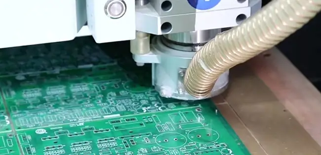
PCBs, the ones that are able to secure fast data transmission rates and ensure signal fidelity, cover different industries and sectors and other components. Here are some of the latest applications:
- 5G Communication: Fundamental to accelerating the transmission of information as well as reducing latency in 5G systems.
- The Internet of Things (IoT) helps to build up the system of communication with each other between IoT devices for the purposes of smart house, industrial, or healthcare applications.
- Automotive Radar Systems: Utilized in the realms of ADAS as well as vehicle autonomy for preventing collisions and obstruction of traffic.
- Aerospace and Defense: Radar systems, communication systems, electronic warfare systems, etc. are Amazonas-specific.
- Medical Imaging: MRI machines and CT scanners rely on this in order to provide high-frequency signals.
- High-Speed Computing: A vital part of HPC systems where data moves between compute and memory, faster data processing and communication, or faster signal flow rates.
- Industrial Automation: Enables remote and automated control and monitoring of equipment and implementation, mainly in factorial circumstances.
- Satellite Communication: A fundamental source for transmitting and receiving signals in satellite communication systems.
- Consumer Electronics: Based on these technologies, data transfer on phones, tablets, and other devices is done at a high speed, and the data processing is automated with electronic components.
- Research and Development: Used in physics and engineering laboratories mostly for creating feasibility prototypes of high-frequency digital devices and systems.
Two common approaches to setting controlled impedance transmission lines
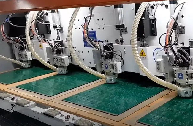
When setting controlled impedance transmission lines on a PCB, there are two common approaches:
Microstrip Transmission Lines
The ground trace is on the top layer, with the ground plane underneath. The width out of the path and the distance from the floor plane determine the impedance. The signal is easily distorted, mainly due to the fact that it is simple and narrowband
Stripline Transmission Lines
From top to bottom of the substrate, a signal passes through the layer of ground plane(s). This factor can be calculated based on the distance this trace wire is from the plane surfaces. EMC Problems Solution 1: stronger signal integrity and EMI performance, but device multi-layered and costly.
Conclusion
Intensity PCBs of high letdown are another essential part of modern electronics equivalents, which empower high-speed data transport and communications. In order to attain the highest standards of design and implementation, a great number of factors should be considered, including optimal performance and reliability. For this reason, continuous development of high-frequency PCB or high frequency digital signals technologies will significantly upgrade the prospects of communication and connectivity in the future. When we say analog signal ground this is a ground plane of the high frequency pcb digital signal ground plane.

