In the realm of electronics where every component always an input that plays a vital role, capacitors maintain a position that can be regarded as the silent hero of the systems. You will hardly find one of these tiny but mighty batteries absent in the common electronic products we use daily. They are there to store and release electrical energy, and running our devices seamlessly. The focus of this blog is about how an electric circuit board capacitor plays its role in the proper working of a system. Its types, applications, and functioning are discussed in detail.
Understanding Circuit Board Capacitor
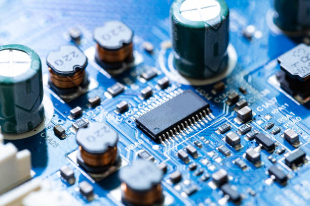
Basically, a capacitor is a passive electronic component which has an electrostatic charge (E) and stored electrical energy in an electric field at its core. While batteries physically store energy chemically in their electrodes, variable capacitors use the electric field between two plates of electrical conductors which are separated by a dielectric as the storage medium.
This design is very basic yet it is really bright as capacitors can fast save and release this stored energy, that they are key components in many electronic circuits.
Types of Circuit Board Capacitors
The circuit board capacitors are available in a variety of designs, a fact which is determined by the nature of the looks and place of application in the particular case.Some common types include:
Electrolytic Capacitors
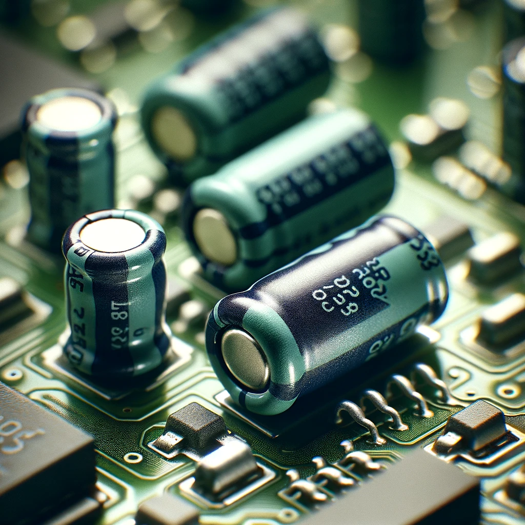
They perform under certain solutions as electrolyte in order to ensure a high amount of capacitance in minimum space packaging. Interestingly, they find application in power supply circuits and audio section also.
Ceramic Capacitors
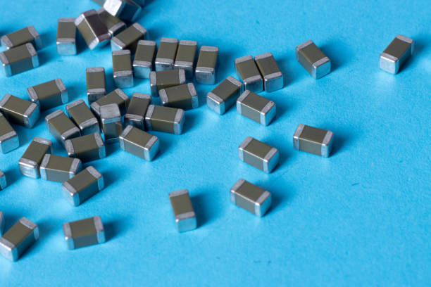
The ceramic capacitors perform perfect jobs and these are the reasons that they are frequently used in high-frequency circuit and decoupling problems.
Film Capacitors
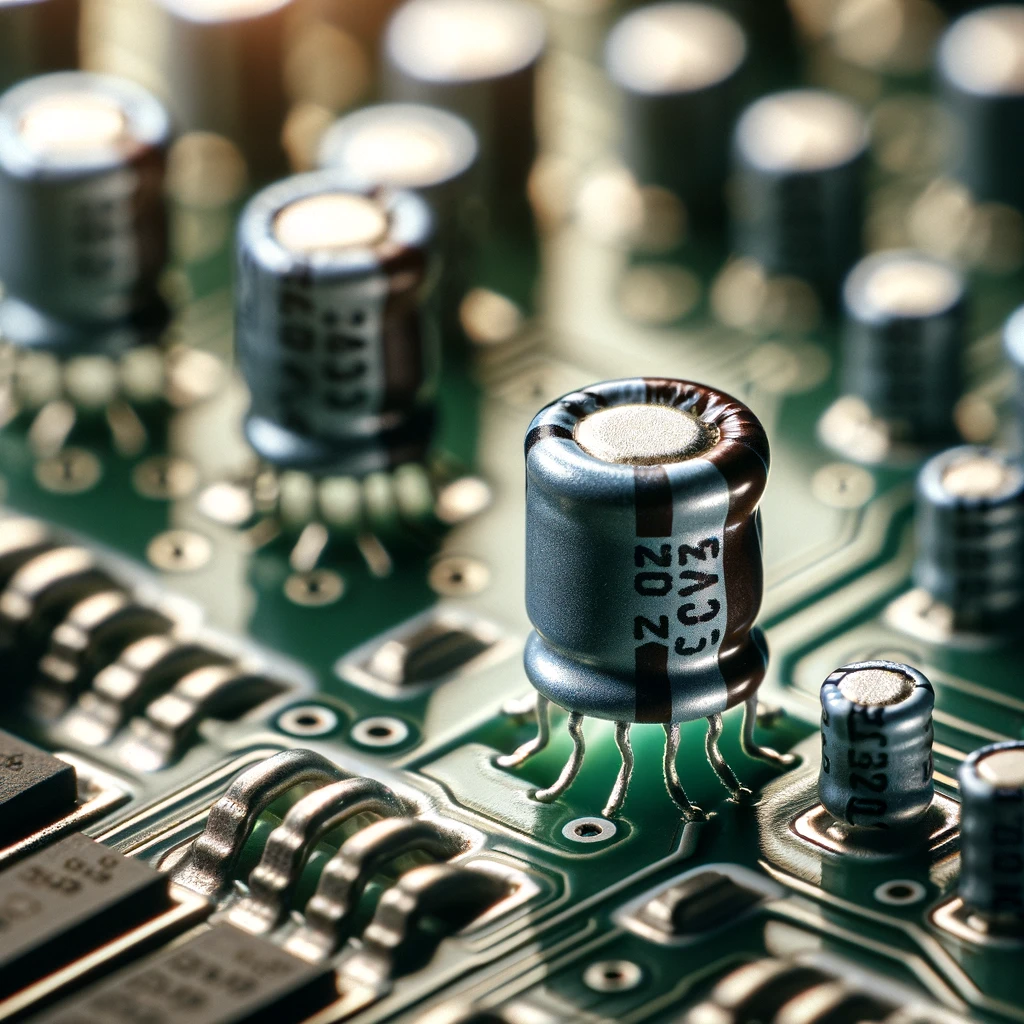
Film capacitors With the help of the low leakage current and high tolerance of the film capacitors to the temperature variations, they are well-known in the industry. These produce signals ranging from timing signals to shaping and motor control.
Tantalum Capacitors
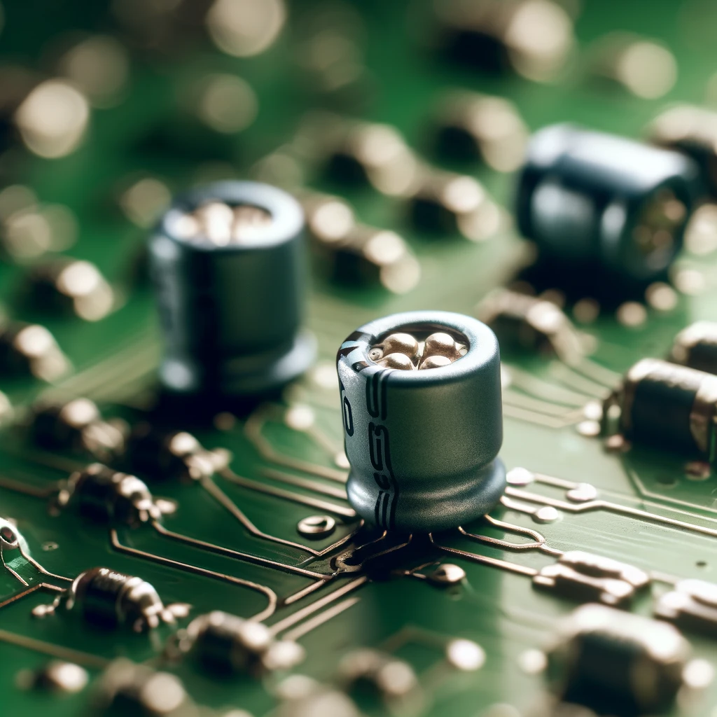
Tantalum capacitators redistribute the bulk capacitors to smaller values through the use of compacted geometry that ideal for general purpose electronic devices and telecommunications application.
Applications of Circuit Board Capacitors
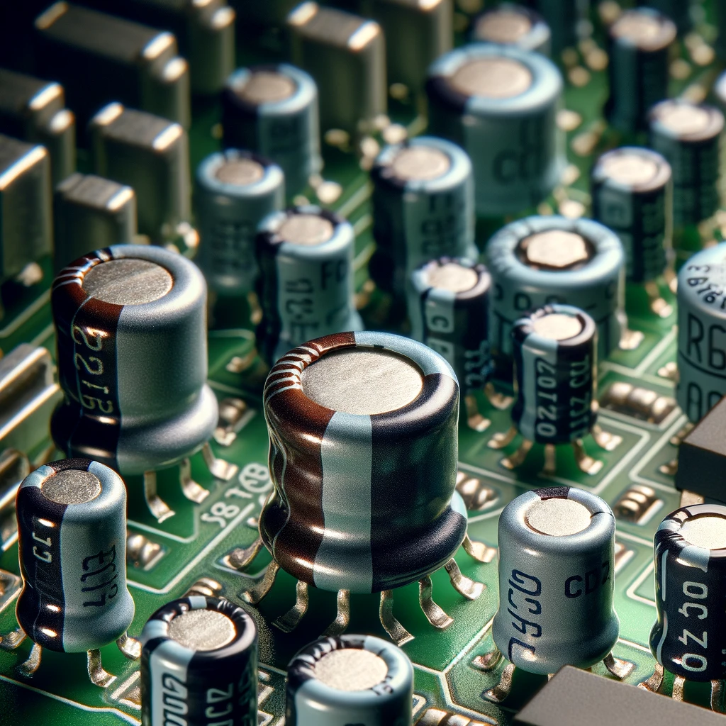
The wide application of capacitors on circuit boards is attributed by the variety in condsitional setups, ranging across industries.
- Power Supply Filtering: This results in by capacitors in electronic power supplies in reducing the fluctuations in the dc voltage and ensuring uninterrupted, stable and clean power delivery to sensitive electronic devices.
- Signal Coupling and Decoupling: The function of the capacitors is to allow for AC currents to pass through while blocking the DC currents over. Therefore, the notch allows signal coupling in amplifiers and power supply decoupling from sensitive circuits.
- Timing Circuits: Along with resistors, capacitors regulate the operation of oscillators and priority guides in electronic circuits.
- Motor Start and Run: The role of capacitors in single-phase induction motors is to adjust the phase of the motor windings. This adjustment results in the smooth running of as well as starting of the device.
How Do Capacitors on Circuit Boards Work?
Certainly! Capacitors on synthetic circuits do this by storing and then letting go of electric double layer capacitors energy. They are built up of the similar theme with the two conductive plates spaced by a dielectric called a dielectric material. When the potential difference is applied between plates, the electrons accumulate on one plate in turn producing negatively charged plate while the equal number of electrons is pulled away from the other plate in producing its positive charge. The applying here establishes a space current field between the plates.
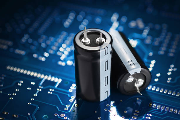
The material acts as an isolator between the plates and then facilitate the increase of the capacitance of the capacitor by reducing the electric field needed to electrically build up a given voltage difference between the plates. Thus, this makes capacitors with different insulating dielectric materials to bear capacitance of different values.
When, a circuit with a capacitor, is put to power, the capacitor charges parallel to the power source, pumping electrical energy by means electric fields between its plates. The capacitor stores this energy right after getting fully charged and then use it when the capacitor starts discharging. The capacitor activates when the circuit needs an additional boost of current, discharging it to the circuit, thus, releasing the stored energy.
One of the main features of this component’s operation is that the capacitor is able to keep a constant voltage before discharging and charging which becomes handy in various electronics uses such as filtering noise from power supplies, coupling and decoupling signals, as well as timing circuits. An essential function of capacitors is in their capacity to store the electrical charge and subsequently release it pretty fast. This is one of the characteristics that ensure the proper working of the electronic devices they are included in.
PCB Capacitor Markings
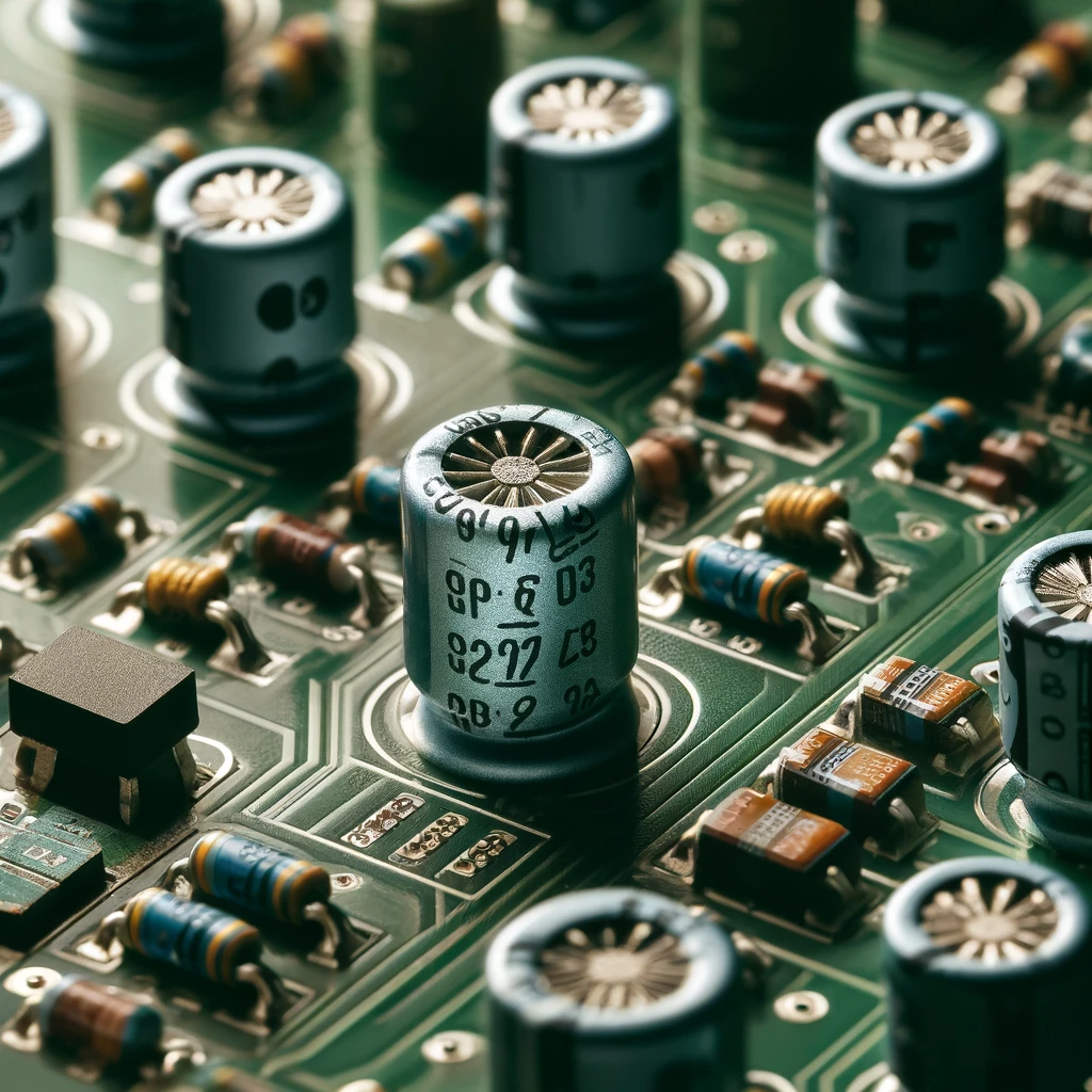
Today, there are symbols of capacitors printed circuit boards (PCBs) which use letters, numbers, and symbols so that to provide information relating to specifications and characteristics of capacitor. These notations can steer engineers, technicians, and hobbyists to choose most relevant capacitors in the market and work for errors correction. Here’s a breakdown of common capacitor markings you might encounter:
Capacitance Values
The value of capacitance is shown as a number followed by a symbol for the unit such as microfarad (μF), picofard (pF), or nanofarad (nF). As an instance, reaching a value of 104 can be evoked as 10 × 10^4 pF, which is equal to 0.1 μF.
Tolerance
Capacitors have a tolerance which describes the deviation that can be allowed by the given capacity value. Generally tolerance values for capacitors are ±5%, ±10%, ±20% or so, and they are usually denoted by a letter code or a percentage symbol (%) following the C value, such as C4725V.
Voltage Rating
The maximum voltage which the capacitor can stand without the due risk of damage is indicated by a number like this, followed by the unit which is either volts (V) or kilovolts (kV). For example,the voltage “25V” on a capacitor means that such capacitor can endure a maximum voltage of 25 volts.
Temperature Rating
Some capacitors are produced with temperature coefficient or designated a maximum operating temperature. This suggests the safe temperature range within which the capacitor can still function a little bit without too significant degradation performance.
Dielectric Material
The kind of dielectric material that is used in the capacitor is marked sometimes by the letter code By and large, the dielelectric materials that people use mostly comprise ceramic (C), tantalum (T), polyester (M), polybromide (P), and metallic foils among other materials.
Polarity
Electrolytic capacitors are the polarized components that must direct the installation in an exact manner for correct operation. To show capacitor’s polarity, than electrolytic capacitors marked have a plus (+) lead and a minus (-) lead. It is critical to pay attention to polarity when installing electrolytic capacitors so you don’t burn out the component nor the Circuit.
Manufacturer Code
If capacitors, the codes or logos of the manufacturer can be seen as it is one of the brand or company that they manufactured. This kind of markings may be live with information about about the capacitor’s quality, life expectancy, and origin of production.
It should be remembered to look on the datasheet or the document providing the details and requirements of the capacitor produced by the manufacturer. As a plus, you would be able to use a multimeter or a capacitance meter which enables you to lift the hood and verify the actual capacitance value and other parameters of the capacitor. Deciphering capacitor markings is a skill for engineers and hobbyists as it helps them to incorporate the correct elements into their electronic circuits and deliver superior power and stability.
Measuring PCB Capacitance
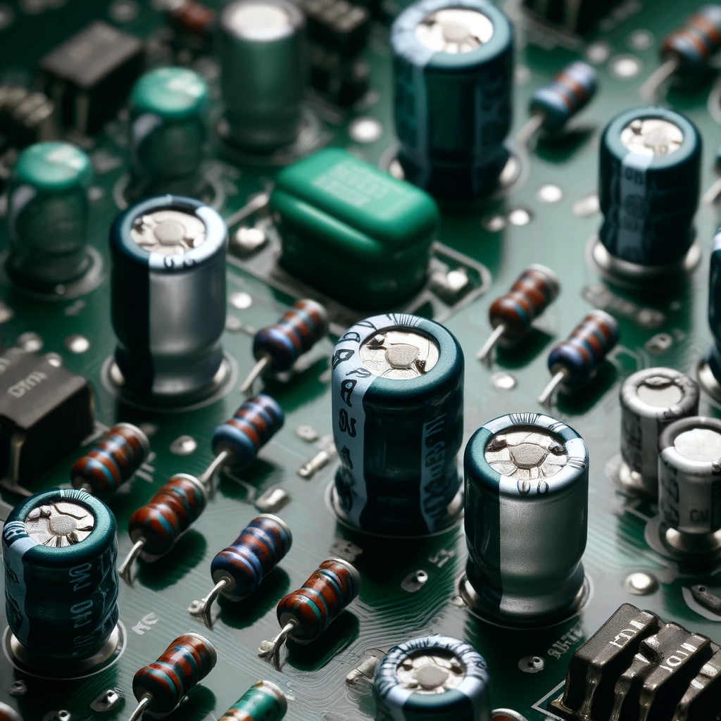
The method of measuring capacitance of capacitors on a printed circuit board (PCB) is not complicated; these measuring devices can be applied either by using a capacitance meter or a multimeter having a capacitance measuring function. Here’s a general guide on how to measure PCB capacitance:
Tools Needed:
- Capacitance indicating multimeter meter for the detection of gaps.
- The measurement PCB is centered round the capacitor to be measured.
Procedure:
- Prepare the PCB: To make sure that the PCB is disconnected from any power source and no voltage is across the capacitor that you are going to measure, you should follow this step. When lead of the capacitor is part of a circuit, you should desolder one of its lead. Thus, a capacitor becomes isolated to check its value using a multimeter.
- Set Up the Multimeter: Turn on your multimeter and go over to the capacitance measurable range. The picture “C” located next to the capacitor symbol is usually used as the most identifying mark. Auto ranging multimeters will find and set the capacitance based on what the multimeter is capable of reading. In case you don’t know the range of the expected capacitance of the capacitor you’re working with then look it up. Otherwise, select an appropriate range.
- Connect the Probes: Capacitors are polerated (e.g., electrolytic). Hence it is indispensable to ascertain that the multimeter probes are connected to the right polarity. In this circuit, the connection should be red probe (red) to the positive lead of the capacitor and black probe (black) to the negative lead. The polarity of the capacitor is immaterial in case of a non-polarized capacitor (say, ceramic).
- Measure the Capacitance: The multimeter probe needs to be placed across the two terminals of the capacitor. Keep the probes during the test and wait for the multimeter to reach the steady state and display the capacitance reading. The actual capacitance value is shown on the multimeter in farads (F) or any smaller unit depending on the range such as microfarads (μF) or picofarads (pF).
- Record the Measurement: Note down the correct value of capacitance measured. When you test the capacitors on the PCB, if you perform multiple capacitors, repeat the process for one.
- Interpret the Results: Compare the capacitance value that has been measured with the capacitance that was expected or expected on the capacitor itself or on the PCB documentation. Make sure to dispose the value of capacitance inside the tolerance range of the application.
- Reassemble the PCB: Finally, if you desoldered any leads to isolate the capacitor, you can re-solder these pins in place, as required, once the measuring is done.
This procedure will ensure that the capacitors, being located on a printed circuit board, are within the acceptable range to ensure their proper performance which is vital for the right application.
Capacitors in High-Frequency PCBs
Capacitors are of utmost importance in high frequency printed circuit boards (PCBs), where signals change rapidly while perfect signal quality matters for more successful products. On the other hand, capacitors find wide usage in most applications, some of which are decoupling, filtering, impedance matching and coupling signals. Here’s how capacitors are used in high-frequency PCBs:
Decoupling Capacitors are used
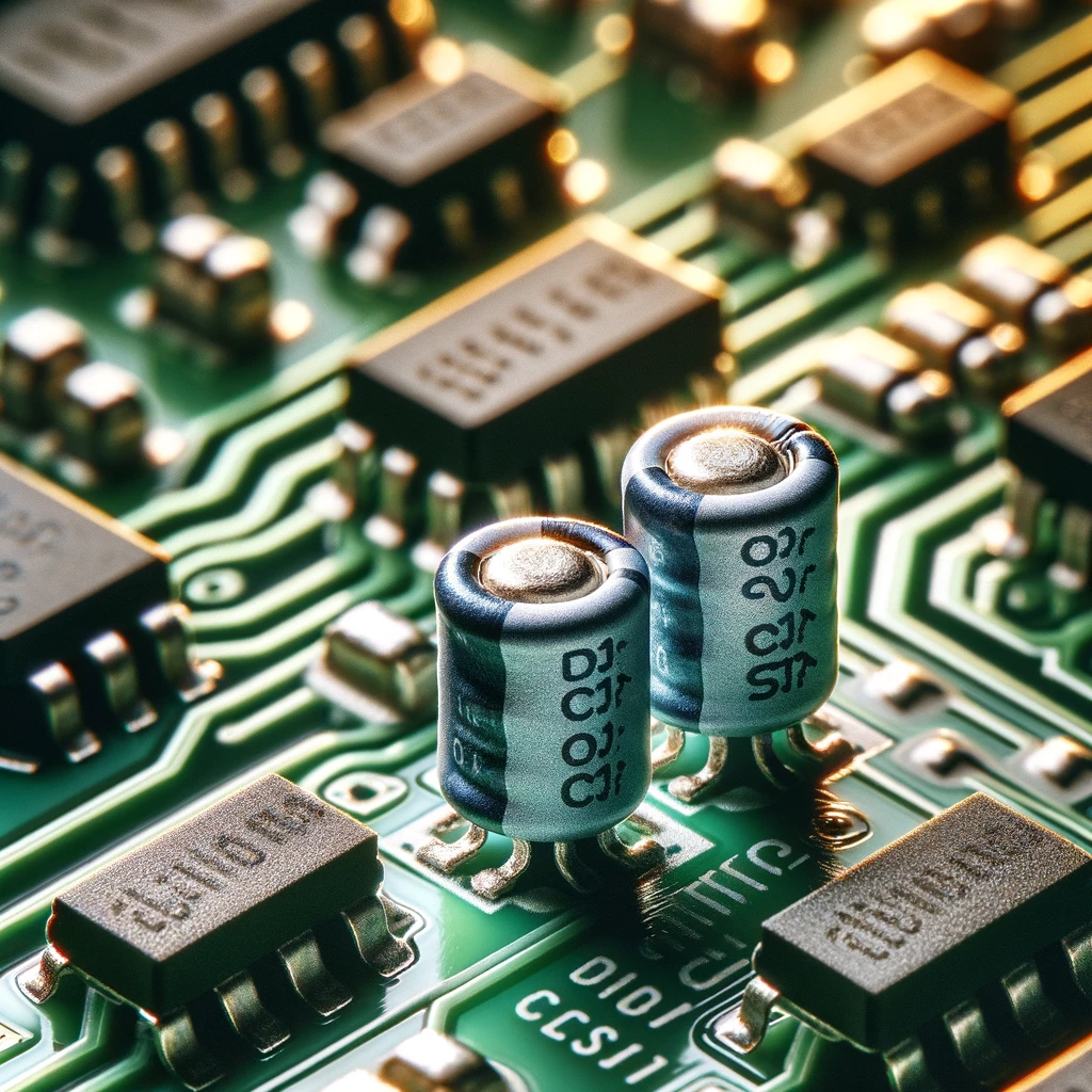
oscillating circuits generate fast voltage fluctuations. Thereby the noise is added to the signal and its quality is deteriorated. Capacitors, during the decoupling, are a good way to ensure that voltage is at its optimum with the impedance path being as low as possible; which at the same time helps in filtering the noise on the power supply lines. The sweep of these capacitors ensures a stable power supply for the sensitive warefare, hence minimizing any signal degradation so as to enhance overall circuit functionality.
Filtering Capacitors are used
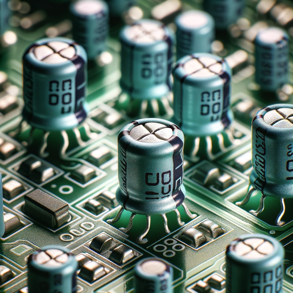
A high-frequency signal is particularly at risk of interference and noise creation during communication process since they contribute to deterioration and ineffective operation. Filter capacitors which are commonly installed at the input and output sides of circuits or where there is only one signal path help to decrease unwanted noise and interferences resulting in accurate and clean signal transmission. These capacitor circuits as frequency selective filters for the signal enhancement via attenuation/blocking of the frequencies that are not desired and EMI reduction.
Impedance Matching Capacitors are used
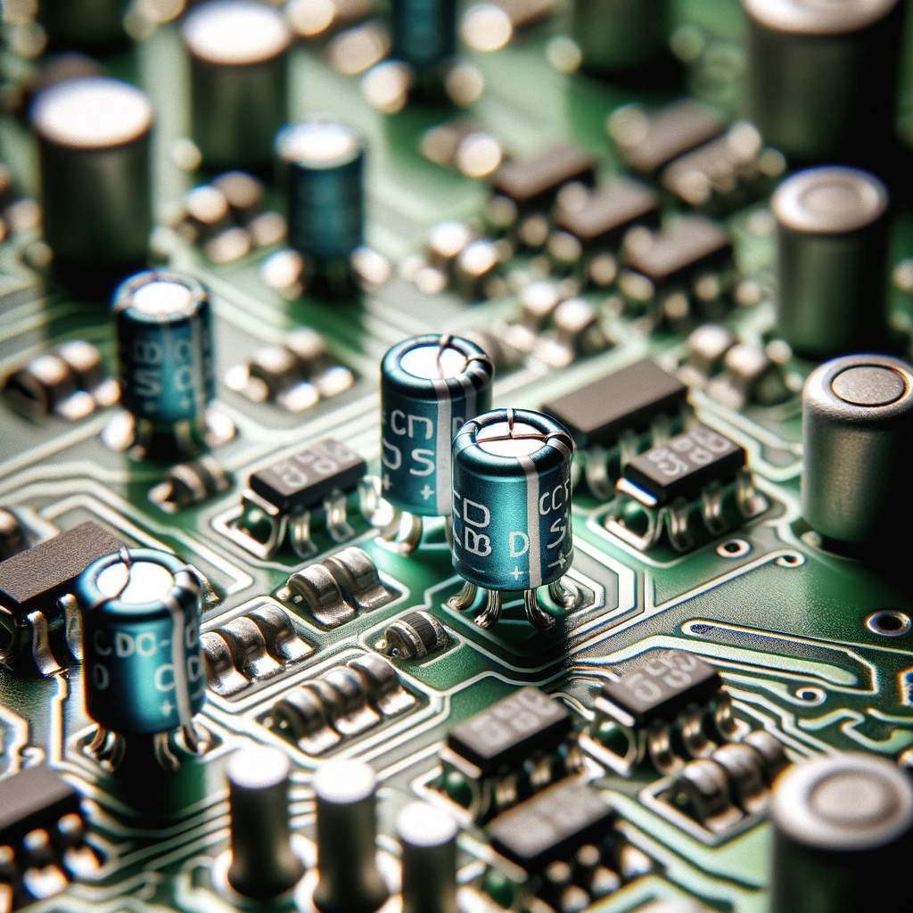
In RF (radio frequency) and microwave circuits, the issue of matching impedance is critical for the effective transfer of power with minimum signal loss due to reflection. Capacitors when instruments are utilized jointly with other inductors, resistors and propagation lines to equal impedance of the components with the transmission lines to the characteristic impedance of the circuit or system. The fine impedance matching aim of the power transfer efficiency, the reduction of signal loss as well as the system performance are very important, specifically for high-frequency applications because the mismatching will result in distortion and signal loss.
Coupling Capacitors are used
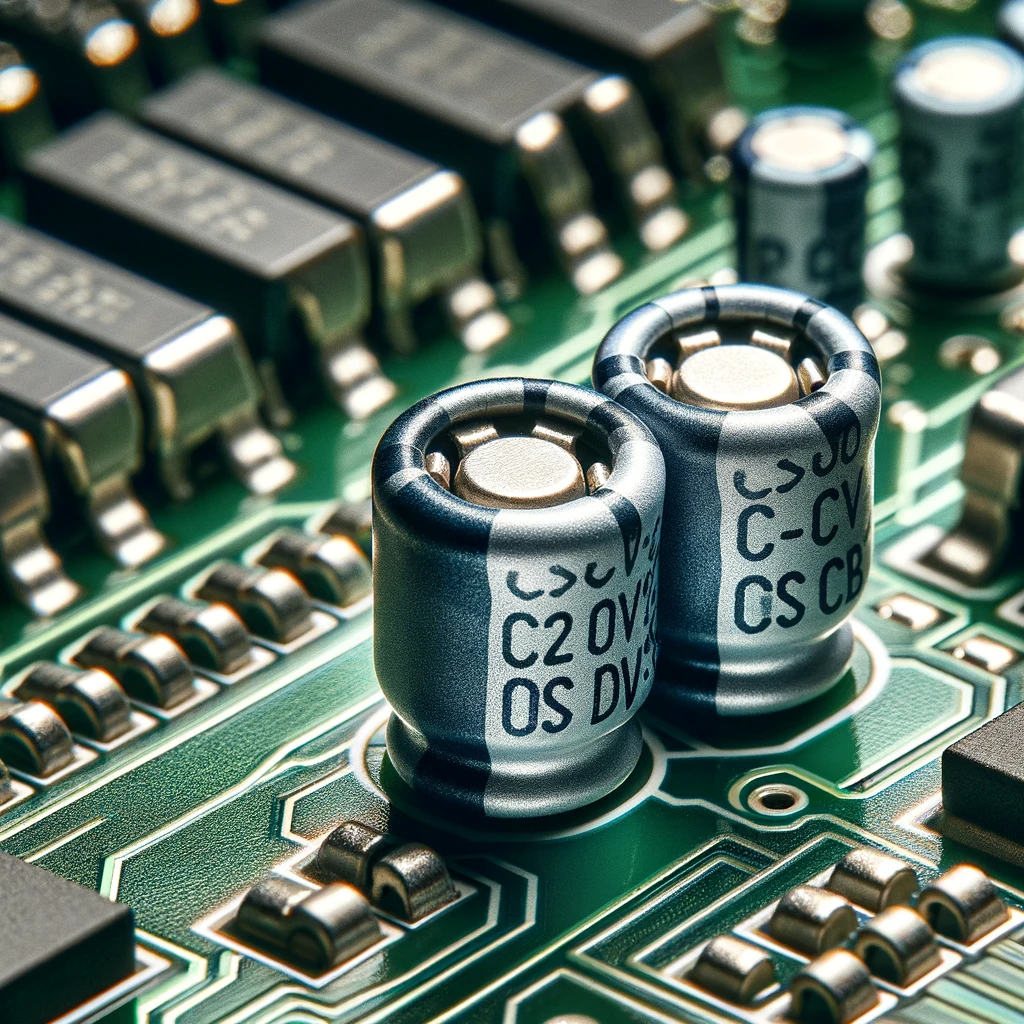
AC coupling to AC circuits and RF circuits exists , where DC components of the signal are blocked , while letting the AC signals . Linking condensers are used to couple or transmit alternating current (AC) signals between stages of a circuit while isolating direct current bias voltage. These capacitors not only transfer AC signals unaffected by the DC working positions of the circuit but also amplify signals fairly.
Tuning Capacitors are used
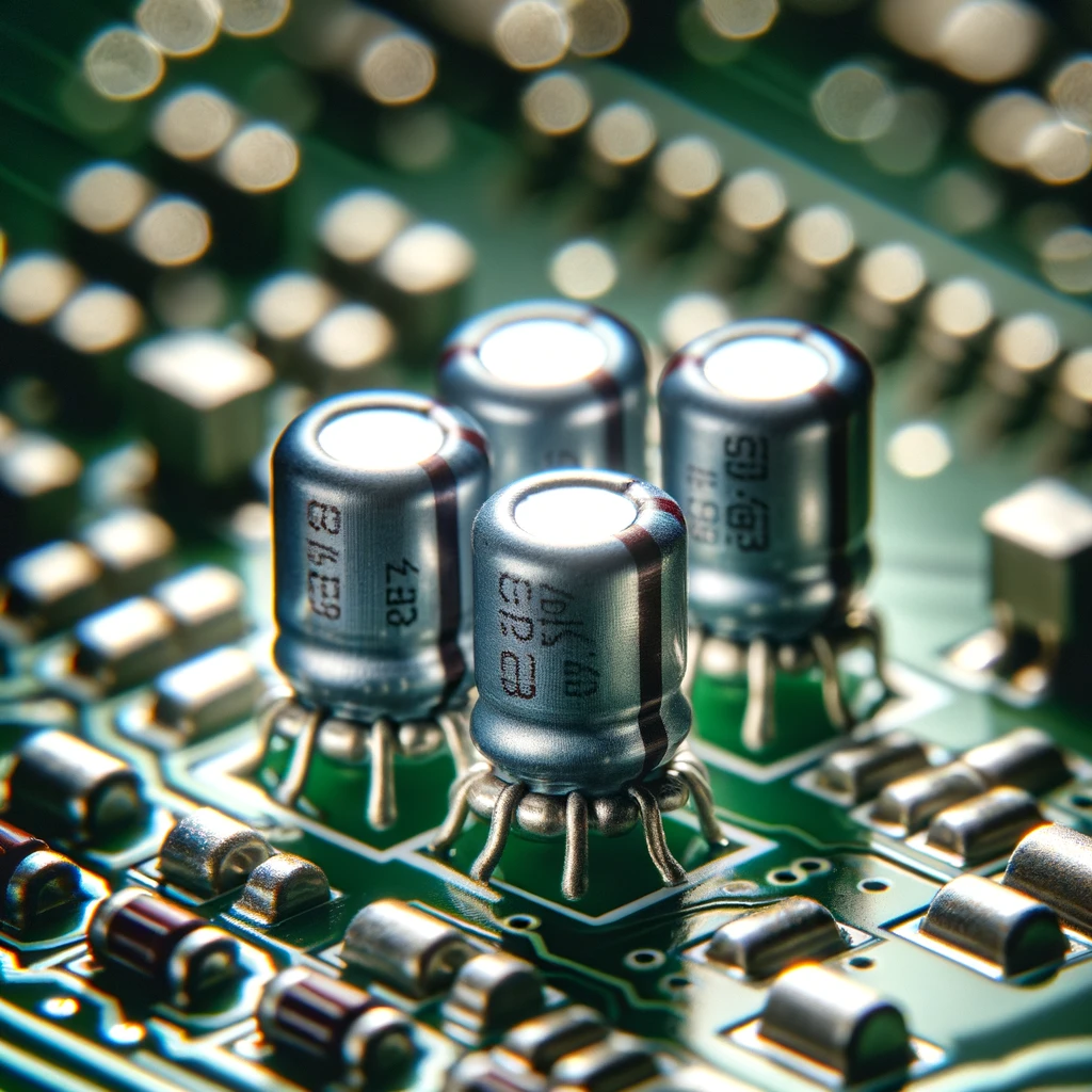
Tuning capacitors are part of RF circuits and antennas as they used as frequency adjustment of circuits to perform optimally. Tuning capacitors can be regulated through the voltage variation, hence, they enable the fine-tuning of frequency and impedance matching; the maximum power transfer and signal reception which are made easy are the effect.
The Role Embedded Capacitors Play in PCB Design
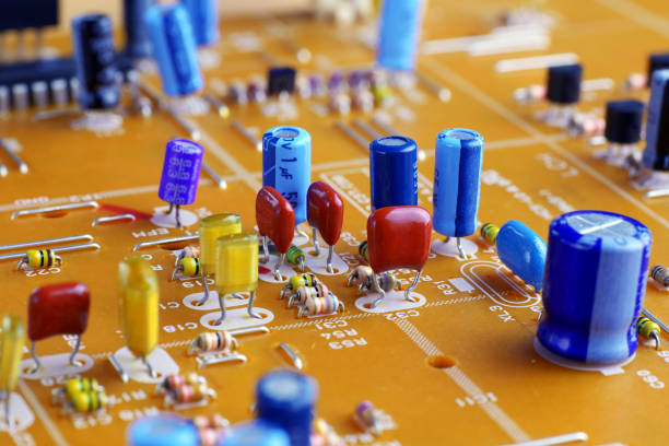
Engraved capacitors are a sort of advanced capacitors embedded straight into the substrate or the layers on the printed circuit board (PCB) substrate and the aluminum electrolytic capacitors, mica capacitors, electrolytic capacitor, ceramic capacitor, polarized capacitors and parallel plate capacitor. What contrasted discrete capacitors mounted on the surface of the PCB and embedded ones is a rather big list, let us explore the main ones. Here’s a look at the role embedded capacitors play:
1. Space Efficiency: Space saving feature of embedded capturing may be one of the major pro’s as far as PCB is concerned. Through incorporating capacitors directly onto PCB circuits, designers reduce the footprint of components used and consequently, they save for other elements and functions. This miniaturization method becomes quite handy when addressing space-saving needs especially in small sized electronic gadgets such as portable devices and small circuit boards where space constraint is a common issue.
2. Reduced Parasitic Effects: Frequency dependent losses, due to induced inductance of the traces and connections of individual capacitors can beset their performance at higher frequencies, Capacitors embedded in the PCB substrate work directly on the PCB without adding parasitic effects; it, therefore, shortens the electric signal path or tantalum electrolytic capacitors and eliminates the number of interconnections simultaneously. However, electromagnetic compatibility (EMC) software minimizes these issues by improving signal integrity, EMI mitigation, and overall performance, especially in high-speed applications.
3. Improved Reliability: Thereby the performance of power supply components is highly improved while wiring and assembly failures are eliminated. The fact that internalization within the PCB substrate results in protection from such environmental factors as mechanical stress, vibration and humidity, which can reduce the reliability of surface-mounted capacitors, makes them more preferable. These mechanisms enhance a robustness, thus making automotive capacitors suitable for applications capable of harsh operating environments and those with long-term operation reliability conditions.
4. Enhanced Thermal Management: Effective heat dissipation is one of the most crucial factor in the electronic design especially in the circuit board of high power and high density. Capacitors that come with the PCB design are an important aspect when it comes to good thermal behavior. They even out the heating of the layers and remove heat faster. This facilitates the creation of optimal temperature distribution, protects nearby elements from heat damage, and improves the entirety of the electronic circuit board performance
5. Cost Savings: In the outset, we notice that the capital investment in direct capacitor technology is higher than in traditional discrete capacitors, but in the long run, the advantages in cost can be witnessed. Discretionary parts as well as assembly labor, and the related surface area, which is treated by the embedded capacitors, can be simplified to minimizing the manufacturing process, material costs, and the goods supply.
6. Design Flexibility: Embedded capacitors are more convenient for designers since they are featured with a variety of capacitance compared to outside discrete capacitors. Manufacturers can incorporate various capacitive values through different sizes, shapes, and placements to suit certain designed parameters. This particularity benefits a lot in several aspects such as making the PCB flexible, improving the signal paths and significantly improving the ability to the function of the complex electronic systems.
Why Do We Need Capacitors?
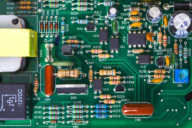
The capacitors are fundamental part of electronics because it houses the energy, attenuates the voltage fluctuation, sends the signal, sets the time, matches impedance, starts electric machine, and filter the pulses from an electrical circuit. These devices are greatly needed especially to provide power to quite larger electronic devices so as to keep them operating and reliable by storing the energy, signal conditioning, and so some other functions especially into the capacitor plates.
Why are capacitors very important?
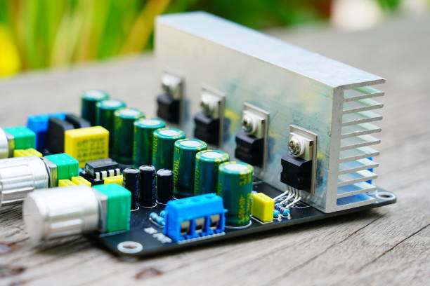
Caps have got substantial relevance in electronics because of their core functions of keeping and giving out electrical energy, filtering to reduce noise of power supplies, make signal coupling between various components of a circuit, timing operations, and impedance matching in high-frequency environments and has strong energy. With regard to their dispensable nature as being the critical parts of all electronic devices that assure a proper and useful device’s function, they are the needed parts of nearly all electronic devices.
Understanding Capacitance value
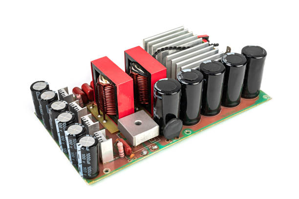
Capacitance value indicates how much a given capacitor can electrically store. It’s like the size of a bucket for holding charge: a ripped bag, a higher capacitance means a bigger bucket. The large capacitors which have higher capacitance store more charges and are used for energy storage task for the capacitors with the smaller capacitance is the timing circuits and high-frequency applications. The need for the right capacitance to exceed in a circuit performance is ensured by capacity matching.
How Much Energy Can a Capacitor Store?
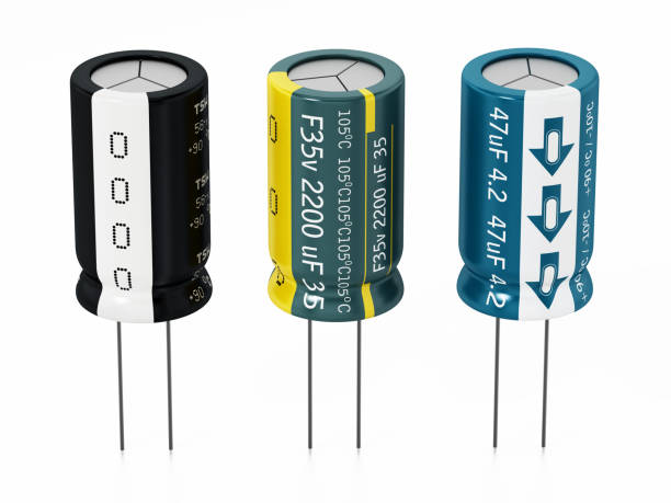
The energy a capacitor can provide is dependent on two factors – capacitance (C) and voltage (V) charged across its terminals. The formula to calculate the energy stored in a capacitor is:The formula to calculate the energy stored in a capacitor is:
Where:
- 𝐸 – E represents the amount of energy that is stored in the capacitor, which in turn is expressed in joules (J).
- 𝐶 – V shows the capacitance of the capacitor (in farad).
- 𝑉-the applied voltage across the capacitor (in volt).
This formula demonstrates the energy capacitor that is being stored is directly proportional to the capacitance square and voltage square. In turn, a capacitor with a high capacitance value or voltage ratings tends to have more energy storages.
It’s worth noting that while the capacity of a capacitor is relative good, it is usually intended for short-term energy storing or to supple quick boost of power instead of the prolonged usability of a battery. Furthermore, the energy stored in a capacitor can be limited by different dimensions such as the capacitor’s physical size, the material it is made of, and the electrical properties of the insulator used.
The Importance of Capacitors in PCB Design
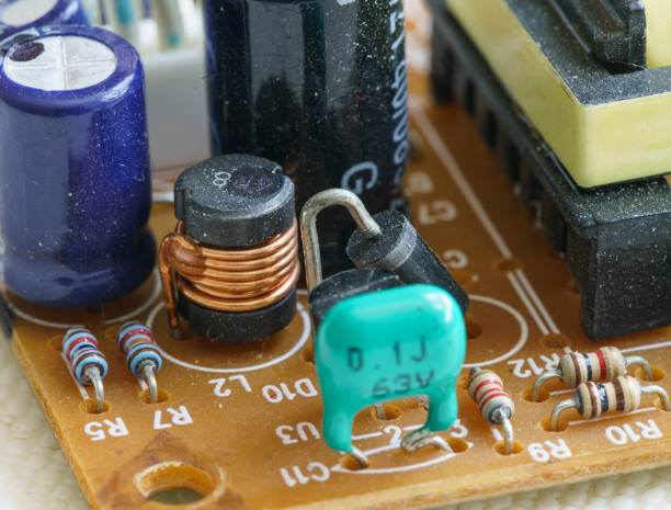
Capacitors have become key components in the making of PCBs which have very critical and vital functions while allowing the electronic devices to perform to the highest standards. They take a much frequent and the most integral role in the process of suppression of noise, steady rate of power supply, normal timing of the circuits, and signal coupling, as well as storing the energy. Besides, capacitors engage the impedance matching, motor operation, and temperature compensation in electronics systems making. With their specific electronic structure, they (i.e. nanoparticles) enable fast and steady power delivery, smooth out electromagnetic interferences as well as miniaturization for excellent and well-functioning devices. In fact, it’s the capacitors, which are the important and necessary elements in printed circuit board (PCB) design, helping to provide the best performance and the functionality given to electronic systems that are used in different applications and industries.
How to Select PCB Capacitors for Your Design?
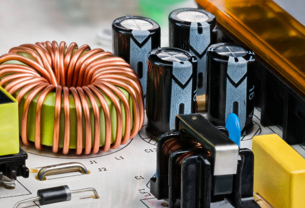
Selecting PCB capacitors involves several key steps:
- Define circuit requirements: Comprehend the volts, capacity, frequency, and temperature requirements.
- Identify capacitor types: Capacitor selection from ceramic, electrolytic, tantalum, or film with according qualities.
- Calculate capacitance: Ascertain the amount of capacitive level needed for circuit execution.
- Check voltage ratings: Be sure that the capacitors can bear up the maximum circuit voltage leaving space for a small safety margin.
- Consider frequency response: Choose capacitors with low ESR and ESL as high-frequency requirements. If this was helpful, please press the thumbs up button.
- Evaluate temperature stability: Choose capacitors with high stable capacitance through temperature operability, and so on.
- Check size and mounting: Make sure all components fit into PCB layout without causing any difficulties during assembly.
- Review reliability: Analyze endurance, temperature rating, and reliability data from well-known producers to verify their reputation of top quality products.
- Consider cost: Try avoiding demanding performance by tightening the budget.
- Prototype and test: Prove the desirability of performance in real-life settings before the design; hence, making it hard to displace in after options.
Tips on How To Place Your PCB Bypass Capacitors
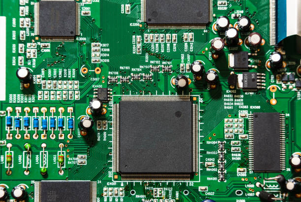
To effectively place PCB bypass capacitors, consider the following tips:
- Proximity to Power Pins: Place capacitors at “power supply pins” that are considered as power points of integrated circuits (ICs) to reduce inductance and impedance of power distribution network.
- Multiple Capacitor Values: Use a mix of capacitor values suited to cover a wide frequency range and therefore achieve adequate noise source suppression.
- Decoupling Hierarchy: Work in a descending order, starting from replacing large capacitors (e.g., electrolytic) in the latter possible location and installing small capacitors (e.g., ceramic) closer to ICs in the next phase.
- Symmetrical Layout: The symmetrical topology would make it possible to evaluate the signal impedance together with equal to equal capacitors-to-power pin distance, preventing the signal integrity problem.
- Short Traces: Make the legs connecting capacitors and pins as short as practical to reduce the parasitic inductance while the resistance is also minimised.
- Daisy-Chaining: Link the capacitors up in a daisy-chain topology as well as in a loop with a reduced area and a low inductance in the network of power distribution.
- Parallel Placement: Split a Layer For Power and Ground Planes into parallel capacitors helps to easily work on coupling and decoupling of high-frequency noise.
- Thermal Considerations: Thermal management is another issue to be addressed, so it is necessary to keep the capacitors away from the heat source because temperature plays significant role in the capacitors performance.
- Signal Integrity: Do not forget signal integrity and position fewer capacitor near signal traces of high-speed analog or digital which are sensitive to prevent noise coupling.
- Prototype and Testing: Design the PCB PCB layout pattern and do testing that is through so that effectiveness of capacitor positioning in decreasing noise and also in keeping power transitions constant can be ascertained.
The risk or hazards of Printed circuit boards
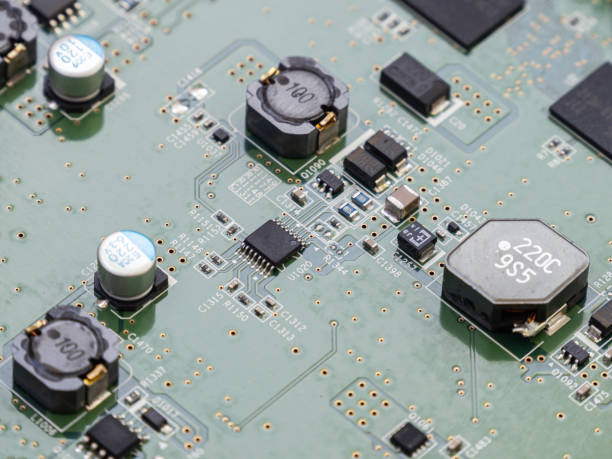
Here are some potential risks and hazards associated with PCB capacitors:
- 1. Electrical Shock: The fact is that capacitors enable stored electrical biggest electrical charge even after power is disconnected. If this is not properly neutralized, electrical shock is definitely possible. Efforts to reach charged capacitors with the bare hands can lead to burns or electric shocks.
- 2. Overheating and Fire: Capacitors have the tendency to overheat when they’re over-voltaged or over currented, or if surrounded by high temperature environment. This can lead to thermal runaway with the possibility of fire or damage to other complex components. In this category, the capacitors are divided into types and among them the electrolytic capacitors are the most vulnerable and certainly they will release their content and even explode if they feel overheating and could be over-voltaging.
- 3. Component Failure: Capacitors might be prematurely damaged by overvoltage, severe overcurrent, stress from high temperature, mechanical stress, manufacturing defects or there might be some problems which are caused by the environment. The capacitor inadequacy can potentially cause circuit shortcomings, loss of features or, in worst case, the damage to other components.
- 4. Leakage and Chemical Hazards: Electrolytic capacitors has an electrolyte solution inside which can leak, if the capacitor is subject to damage or reach its end of life. Contained in the catalyting liquid could be corrosive or toxic compounds that not only will affect the environment but also endanger human health.
- 5. Environmental Impact: Even improper disposal of PCB capacitors, particularly those with electrolytic capacitors soluble in hazardous chemicals can create a threat to environment since these substances can be washed out to the ground, water, or air. It is important to conform to recycling and disposal standards of electric components if you want to leave the environment at a less impacted state.
- 6. Reliability Issues:Failure to capacitors may cause problems with the reliability of devices and systems. The outcome is that one will experience the issues of the extra maintenance costs, downtime, and potential safety risks. The faulty line capacity capacitors in turn can cause system breakdown, data loss, and equipment damage especially in a critical system like healthcare, space, or automotive.
- 7. Counterfeit Components: Concerning the number of imitation electronic elements, such as capacitors, is attributed to the fact that they provide a prospect of lower quality, performance, and reliability. Fakes may not correspond to the definite specifications or quality standards that cause hazards in safety and reliability in electronic devices engineering.
Handling PCB Capacitors
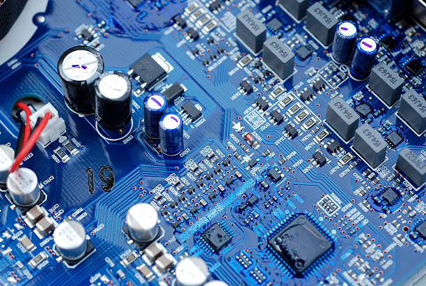
PCB capacitors should be handled safely by discharging them, avoiding electrostatic discharge (ESD), stressing and injuring fragments of the components, minding the polarity, preventing overheating, protecting the boards, inspecting them before use, assembling them properly, repurposing them adequately, and treating with caution.
Storage of PCB Capacitors
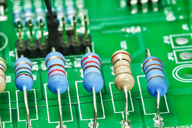
The use of efficient storage is a crucial element in maintaining all capabilities of PCB capacitors and reliability. Here’s how to store PCB capacitors effectively:
- Climate-Controlled Environment: Keep capacitors in a dry climate controlled room maintaining less variation in temperature and humidity because moisture absorption might damage them.
- Avoid Extreme Conditions: Shield capacitors from radical temperature, humidity, direct sunlight and heat sources in the form of these will deprecate performance and destroy the component materials.
- Secure Packaging: Respect the original capacitors packaging and store them in anti-static bags, moisture-proof containers or seal the box in order to prevent dust, moisture and physical damage.
- Labeling and Organization: Undoubtedly, placard all the capacitors with the specifications, the part numbers as well as storage duration to make sure of the ease of determining and stocking. Structure the capacitors in a precise way such that they cannot be wrinkled and also it should provide easy accessibility.
- Avoid Mechanical Stress: Be cautious when handling capacitors not to mechanically stress or damage them by drops and impacts during storage, handling and transporting. Avoid the stacking of heavy objects on top of capacitors or applying a pressure that is beyond the intended capability of the component.
- Rotate Stock: Practice a FIFO system for capacitors rotation to exchange older batches with progressive ones to avoid long-term storage which leads to degradation.
- Monitoring: Perform random checks on stored capacitors for evidences of damage like bloating, leaking or cracked dome. Recycle any components that are broken, and resort to purchasing new ones if the others can not be fixed.
- Segregation: Keep capacitors of different types apart by storing them separately to prevent cross-contamination or mixture of components. Categorize electrolytic capacitors from either ceramic or film capacitors since there are chemical reactions between them.
- Compliance with Manufacturer Recommendations: For the best performance and reliability of capacitors, always adhere to manufacturer guidelines and recommendations as far as safety precautions and storage conditions as well as when handling.
Capacitors In High-Frequency PCBs
As the frequency on high-frequency PCBs increases, capacitors become very effective in canceling out fluctuations of the power supplies, filtering the noises, matching impedances, and coupling and tuning circuits. To this end, they help in signal optimization, reducing interference, and making the transfer of power efficient in higher frequency applications.
Conclusion
Circuit board capacitors may be small in size, but their impact on electronic systems is immense. From filtering power supplies to timing circuits and beyond, capacitors play a vital role in ensuring the smooth operation of electronic devices we rely on daily. By understanding the different types, applications, and principles behind circuit board capacitors, we can better appreciate their significance in the world of electronics.
Next time you hold a smartphone, operate a computer, or use any electronic device, remember the unsung hero—the circuit board capacitor—that quietly powers our modern world.

