In the electronic world, where performance and trustworthiness are crucial considerations, which printed circuit board thickness uniquely copes with becomes a factor to ponder. PCB core thickness plays a role in resistance to damage, electrical ability, heat dissipation, and mechanical stability.
In this article, we will review the topic of PCB thickness and indicate key moments for the selection of PCB, as well as observe its influence on the reliability of electronic designs as a whole.
Understanding PCB Thickness
The PCB thickness refers to the upper and lower parts of the board, which are measured by the copper layers. The copper layer thickness is shown by the number of copper layers. The paramount factor that cuts down on the level of signal transmission and the electronic operation of the parts, as well as the mechanical strength and manufacturing process/compatibility of the PCBs, is distance.
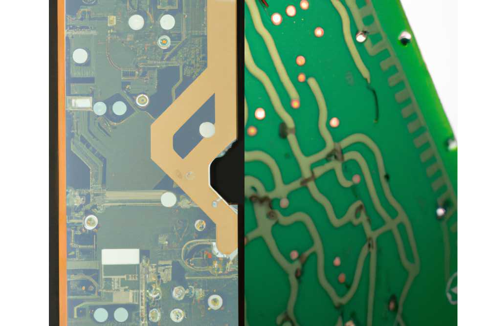
Thicker PCBs are preferable for applications that require more strength, such as industrial complexes or automotive electronics. Moreover, they influence impedance, signal integrity and thermal conductivity. Component compatibility should be on designers’ mind when they choose a circuit board’s thickness.
Importance of PCB Thickness in Electronic Design
The PCB trace thickness goes beyond physical appearance; it is crucial to the operation and performance of electronic devices.
Mechanical Strength: The presence of thickness in the PCB is the primary factor that contributes to its mechanical strength, avoiding such things as bending and warping, especially in regards to temperatures and humidities that vary.
Heat Dissipation: A thicker PCB takes on the job of dissipating the heat from devices being operated in conditions that involve heat as the performance of the devices depends on the operating temperature so as to maintain steady work performance of the devices in the entire life cycle.
Signal Integrity: Thick PCBs are involved in the quality of the circuit and specifically of the high-speed functions that ensure the proper transmission of data and signals on the circuit board with reduced loss and interface.
Component Compatibility: The PCB thickness is one of the key factors in managing the mounting layout and ease of the production assembly. It gives more room for tracks to be inserted and rerouted, which actually boosts the manufacturing process’s efficiency.
Standard PCB Thickness
These are the lists of standard pcb thickness sizes
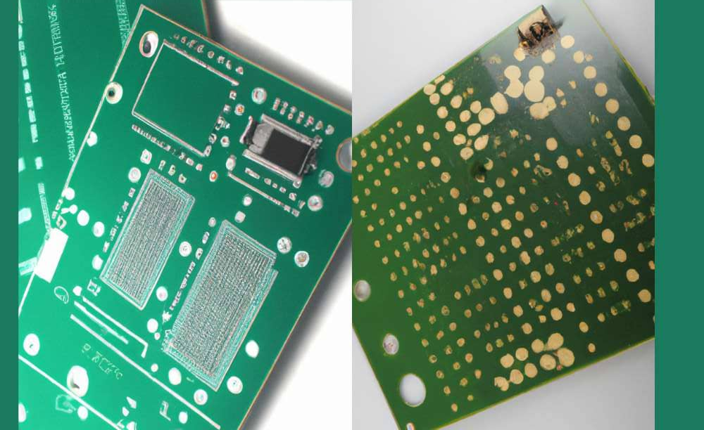
0.063 inches (1.6 mm)
It is a standardized PCB thickness and a typical PCB thickness that has a label of the most popular PCBs. It features the right balance that is so useful for balancing saving materials and the capability of multi-operational usage, such as consumer electronics and industrial equipment. That’s why this is considered the standard thickness of the PCB.
0.093 inches (2.36 mm)
This extra-wide option provides more stiffness and it might help to hold heavier components or other devices that need support in terms of mechanical strength. Generally, it is the alternative of choice in the most common designs or in the case of devices that require superior power or higher number of cycles, such as automotive electronics or industrial controls.
0.125 inches (3.18 mm)
From time to time, these materials may be used in applications requiring additional structural integrity and better thermal management. That thickness, on the other hand, is more found in particular industries like aerospace or military, which mainly need to be durable and dependable.
Factors to Consider When Choosing PCB Thickness
Printed Circuit Boards (PCBs) play a vital role in the current landscape of electronics, as they are where the electronic components are mounted and connected to each other. One of the most notable aspects of a thicker PCB is that this can prove to be very relevant to the performance, reliability, and cost of the board. This article is specifically on the different factors determining PCB thicknesses; those include substrate thickness, prereg thickness, PCB copper thickness, board thickness, and multilayer thickness. These are the factors:
A. Substrate Thickness

The substrate thickness involves the underlay material on which the PCB is designed and built. Numerous substrate materials are available, such as FR-4 (a kind of fiberglass-reinforced epoxy laminate), the well-known metal core materials (aluminum or copper), and materials with high degrees of flexibility, like polyimide. Be it a thicker substrate material selection or its thickness decision, which are among the various requirements and constraints of the application,.
Impact on Rigidity: The stiffer substrates perform significantly better in terms of support and weight handling; that is, there will be fewer mishaps due to mechanical faults.
Thermal Management: Heatsinking technologies on higher substrates would be much better at transmitting heat energy that is vital for the purpose of components with high power or areas with high temperatures.
Cost Considerations: More thick substrates require a higher material cost, and some of those may require even specialized manufacturing, thus increasing the cost of PCBs.
B. Prepreg Thickness
In prepreg, or pre-preg, the epoxy resin layers are impregnated in between the copper layers when laminating for external layers and inner layers of PCB bonds. It is important to note that the prepreg thickness will determine the thickness of the PCB stackup.
Layer Bonding Strength: Building up prepreg thickness is an effective way of improving copper bonding stresses in multilayer PCBs, which leads to a better structural integrity of those PCBs
Electrical Performance: The prepreg thickness might be the cause of signal disruption and impedance characteristics, for instance, in conditions of high-speed signal transmission.
Manufacturability: Using thicker prepreg layers can necessitate processing and material changes in lamination, as well as impact manufacturing’s lead time and expenses.
C. PCB Copper Thickness
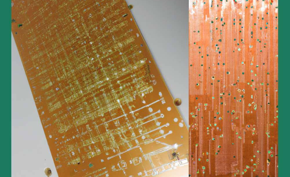
The copper thickness of a PCB means the thickness of copper foil on the copper foils on the board, which is used for conducting electrical signals. Suitable-thickness copies of copper alloys contain 1 oz (approximately 35 micrometers) and 2 oz (approximately 70 micrometers) options, and this may vary depending on your specific project.
Current Handling Capacity: Copper weight tracks can transport more current and hence flow at a higher voltage, resulting in fewer heat dispersions and processing thicker copper (a fact that is required for power electronics and high-current applications).
Signal Integrity: The thicker copper allows for attenuation of impedance variations and signal eddy currents, which starves the quality of the high-speed digital and RF circuits.
Cost and Weight: Thicker copper layers require more material and contribute to the overall PCB core thickness, which would translate to higher material costs and a broader PCB, which are a few worries for PCB manufacturers for mobile and lightweight electronic devices.
D. Board Thickness
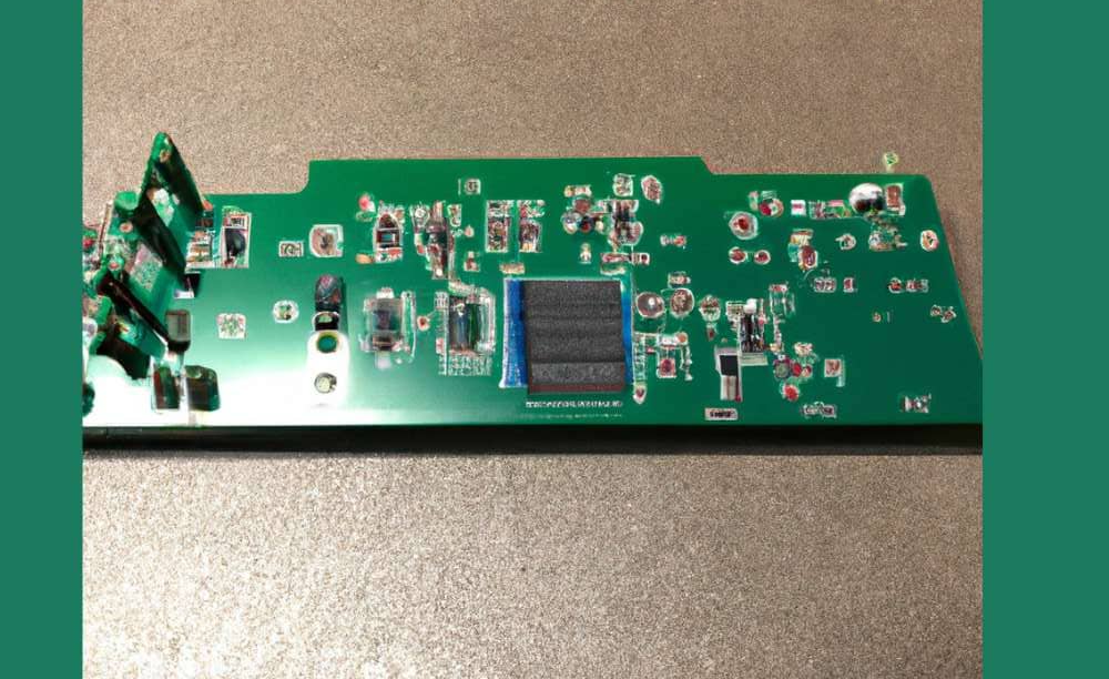
In terms of the thickness of the board, it is taken into account, which includes all layers built from the ground up—substrate thickness, copper traces, and components.
Mechanical Stability: Thicker panels improve mechanical stability; thus, they are less likely to be affected by flexing or warping due to vibrations and subsequent dynamic and mechanical stress.
Component Compatibility: Thick boards can accommodate more power components as compared to lower gauges or give more component density, hence providing design flexibility.
Stackup Design: There is no doubt that the board thickness determines the PCB stackup design process and affects signal integrity and impedance control, and it remains a major performance parameter.
E. Multilayer Thickness
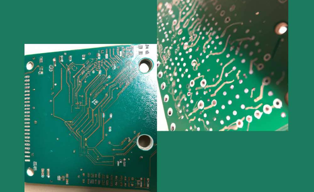
In multilayer PCB construction, the vias interconnect multiple layers of copper trace adjoining each other. These layers are held together by the insulating substrate sandwiched between them. The entire PCB thickness of a multilayer PCB is determined by the number of layers involved in the construction as well as the thickness of each layer type.
Complexity and Density: The increase in thickness of multilayer PCBs results from the alternative of the more complicated circuit design, the higher rates of component densification, and the advanced channel structure.
Signal Integrity and Crosstalk: The inclination of layer width and spacing of multilayered PCBs influences the signal integrity, impedance matching, and interconnections between the adjacent traces. This needs a lot of design considerations.
Thermal Considerations: The complexity of designing and using thick multilayer PCBs can demand additional thermal management approaches like heat sinks or thermal vias in order to adequately dissipate heat.
F. Solder Mask Thickness
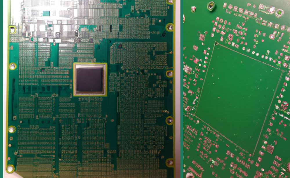
The solder mask is a shielding film placed against the surface of the PCB. In areas where soldering components are needed, the solder mask is not applied. These factors are the thickness of the solder mask, which in turn governs the solderability, solder joint quality, and resistance against elements such as moisture and contaminants. Deciding what the thickness of your solder mask is can be decisive for the reliability of your soldering process and longevity of the PCB.
The appropriate PCB thickness is an integral part of electronic engineering, which is governed by multiple parameters like substrate thickness, copper thickness, and structure, including layer PCB thickness.
Grasping these two factors and their consequences is the fundamental part of developing PCBs that meet performance, reliability, and cost objectives demanding high precision and small repeatable errors across the application range.
Benefits of Optimal PCB Thickness
Optimum signal propagation and best possible reliability of the electronic devices are ensured by selecting the correct PCB thickness. In this section, we’ll dig into the advantages of meeting that mission-critical PCB thickness for your application.
A. Improved Mechanical Stability and Durability
To begin with, there are some key advantages to selecting a standard PCB thickness, including better mechanical stability and endurance. Choose the best PCB thickness for improved mechanical sturdiness, durability, and resistance to muddy conditions.
It enables risk-free continuity under severe conditions and is therefore suitable for reliable endurance in industrial equipment, automotive electronics, and aerospace applications.
B. Enhanced Signal Integrity and Reduced Impedance Issues
The choice of optimum PCB thickness is significant because it ensures proper signal integrity and reduces the level of impedance that occurs in the circuits at high frequency and high speed.
It regulates the signal’s conduction, eliminating electric interference, and effectively conveys signal communication characteristics, especially in telecommunications and data transmission fields.
C. Efficient Thermal Dissipation and Heat Management
PCB thickness has a useful role beyond simply functioning as a substrate or connecting layers. The overall thickness has ballasted things for temperature issue; the components will last longer without overheating. The capability to switch paths in high power densities or adverse environments like electronics and LED lighting is very essential.
With optimal PCB thicknesses, all in the name of thermal performance, the designers can manage the operation, thus eliminating thermal-induced failures and even increasing the overall performance of electronic systems.
IV. Comparison of Standard PCB Thickness Options
These are the advantages and disadvantages
Advantages
- Thicker PCBs provide superior mechanical stability, reducing the risk of bending or breaking, especially in harsh handling or environmental conditions.
- Thicker PCBs offer improved heat dissipation, making them ideal for high-power applications requiring thermal management, preventing overheating, and ensuring component longevity.
- Thicker PCBs enhance signal integrity, reduce crosstalk, and improve overall performance in high-frequency designs by minimizing impedance variations.
Disadvantages
- Thicker PCBs necessitate more material and manufacturing steps, resulting in higher production costs, particularly in cost-sensitive projects or mass production scenarios.
- Thicker PCBs are heavier and bulkier, making them unsuitable for applications with strict weight or size limitations, such as portable devices or miniaturized electronics.
- Thicker PCBs in high-speed designs can introduce signal propagation delays due to longer trace lengths, potentially impacting signal timing and synchronization.
V. Case Studies of Standard PCB Thickness
These are those case studies of a Standard pcb thickness of the board:
1. High-Frequency RF Applications
Case Study: Wireless Communication Systems
In 5G base stations, for example, which are both connected via wireless, PCBs fulfill a vital function through signal transmission and reception. A case study comparing 0.062-inch and 0.093-inch PCB thicknesses for RF modules revealed that: A case study comparing 0.062-inch and 0.093-inch PCB thicknesses for RF modules revealed that:
0.062-inch Thickness: Gives more effective means of signal purity and signal leakage, which is supported by the lower dielectric losses, so the cable is reliable in the most complex digital applications.
0.093-inch Thickness: Strengthens a system force conjunctly with increased signal attenuation as its side effect. Consequently, this creates higher reservations about using the system in very high-frequency bands.
Result: This is the reason for the selection of this 0.062-inch-thick PCB to ensure system compatibility and high performance in tough radio frequency situations.
2. Power Electronics
Case Study: Motor Control Systems
The operating workstation for control of industrial applications must be designed so that PCBs with high supply current and heat dissipation will perform well. A comparison between 1 oz and 2 oz copper thicknesses in a motor drive PCB showed that: A comparison between 1 oz and 2 oz copper thicknesses in a motor drive PCB showed that:
1 oz. Copper Thickness: Adequate power management for low to medium scales is consistent with thermal management for high-power usage scenarios.
2 oz. Copper Thickness: Provides better heating and cooling distribution without problems or thermal issues, with acceptable overall system reliability.
Result: The choice of the 2 oz. Copper thickness was the key factor in the success of the motor-drive system, ensuring its ability to withstand heavy loads without performance degradation.
3. Consumer Electronics
Case Study: Smartphone PCB Design
The manufacturers of smartphones confront the dilemma of getting a crooked portion apart from the hardcore PCB design. A study analyzing 0.031-inch and 0.062-inch PCB thicknesses in smartphone mainboards found that:A study analyzing 0.031-inch and 0.062-inch PCB thicknesses in smartphone mainboards found that:
0.031-inch Thickness: Thinner boards profiles may be possible, but they cause compromised structural integrity and thermal performance as well. Create your own flying machine and explore our world in a whole new way! Unlock the secrets of lift and propulsion, and defy gravity as you soar through the sky.
0.062-inch Thickness: It makes the whole piece resilient to enough heat emissions dispersion and etching processes, thus assuring the appliance remains stable and lasts a long time.
Result: A self-confident design of a smartphone was made possible choosing 0.062-inch PCB thickness that guaranteed reliability and durability of the smartphone without increasing its footprint.
Conclusion
The thickness of the board is one of the variables that facilitates the design of the mechanical part, as it is a structure that holds the electronics together and helps dissipate heat. It also insulates electromagnetic noise interference and keeps the integrity of the signal. First in line is the plank’s thickness; following are the regular specs, which are 0.063 inches, 0.093 inches, and 0.125 inches.
By utilizing the available optimum PCB thickness, you will be able to obtain mechanical soundness that is close to the peak currents while also saving heat. To finally decide, you can consider the factors that are listed, such as price and weight, and the decision will be up to you. A case study can be really helpful for people who work in high-frequency RF, power electronics, and consumer electronics, for example.
The right emerging trend in PCB thickness is one of the things that augments reliability in electronics design. The designers will ensure that the thickness of the PCB satisfies the critical role of guaranteeing optimal performance, increased durability, and reliability in their products by having knowledge of the importance of thickness, analyzing standard alternatives, factoring application-specific criteria, and practicing best practices in associated cooperative endeavors and testing.

