Protoboards, also known as breadboards or prototype boards, are among the essential tools for an electronic prototyping and investigation project. In this way, you are able to generate, prototype, and test a ton of functional electronic circuits without having to solder them. In the following paragraphs, we’ll shed light on these fantastic tools, the types of material in them, and how to employ them to the fullest extent in your product or project.
Understanding Protoboards
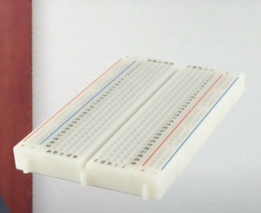
Protoboards are usually rectangular and have a set of holes, resembling a mat, that follow a line in a particular order. They are hole are the cavities where electrical parts like resistors, capacitors, integrated circuits (ICs), complex circuits, and wires are put. hole pattern varies from one learning board to another and it is mostly arranged in such way that components are easily interconnected without soldering.
Advantages of Protoboards
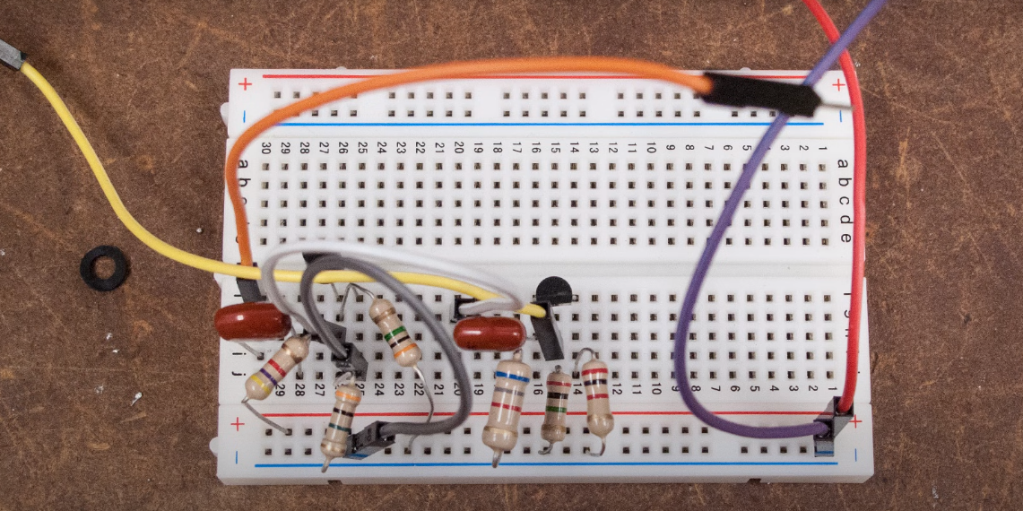
These are the advantages of protoboards:
- Rapid Prototyping: Protoboards are specifically created to allow for the quick and easy construction of simple circuits without the use of solder and are normally used for constructing circuits to be used in actual projects. Protoboards assist inventors in getting their inventions to market sooner than they would have otherwise. Bearing in mind that the different parts of a product are interlinked, instantaneous replacement of these parts is far easier and makes the prototyping process easier.
- Reusable Components: One significant advantage of protoboards is that they are easy to switch out components because there are no soldered connections; this contributes to multiuse of elements and various iterative design and testing for design, which keeps costs low.
- No Specialized Equipment Required: As compared to the Printed Circuit Board fabrication that requires complex machines and skills, the parts can only demand a compliant wire, pliers, and components, with the latter being easily accessible for beginners and hobbyists.
- Flexibility: The prototyping boards bring the idea of permanent circuits as well as temporary ones into the equation; some of the solder and multiple parts can be moved around in order to test numerous configurations.
Disadvantages of Protoboards
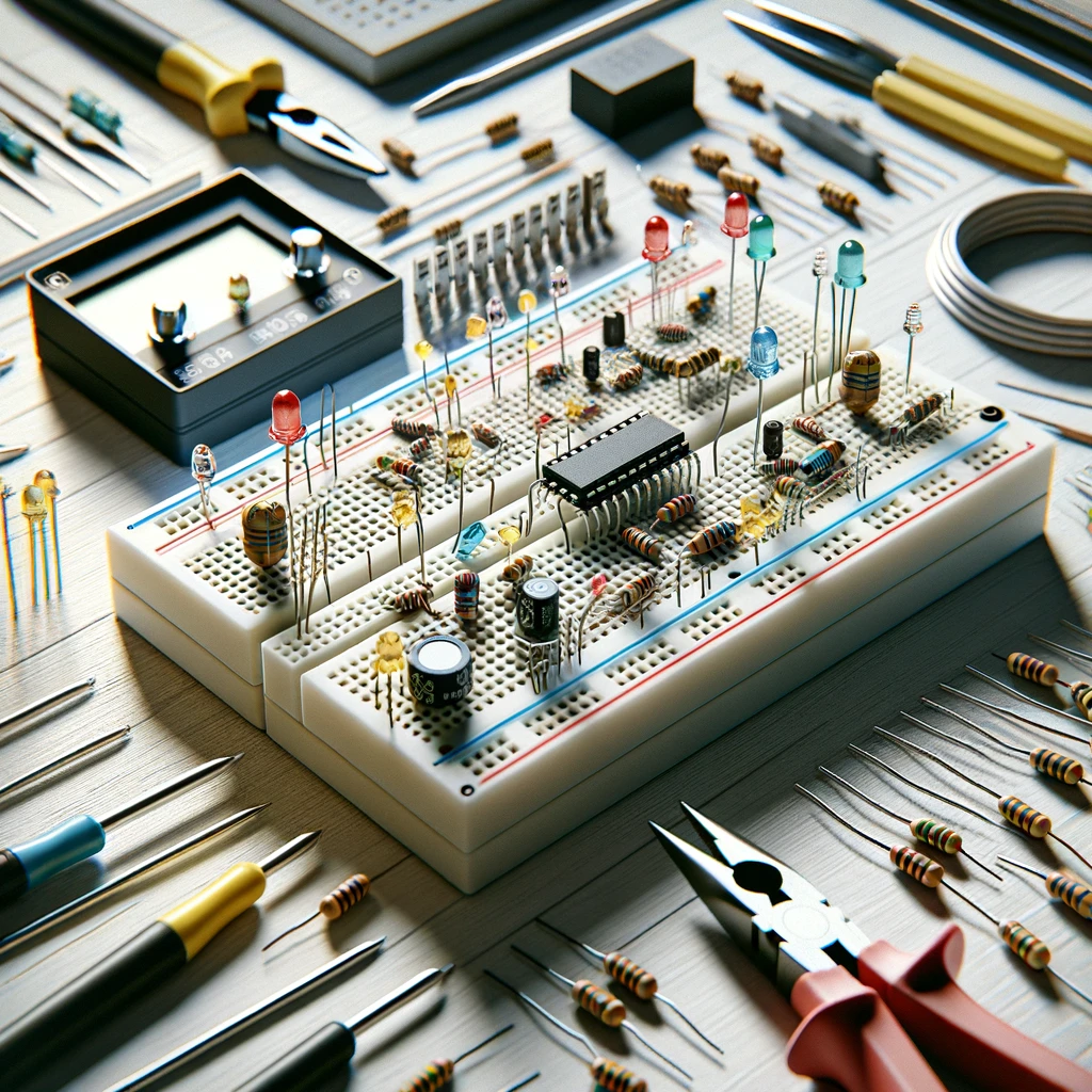
As you can see, there are also advantages, but you can also read about the disadvantages of protoboards:
- Limited Durability: Note that protoboards are not built for projects to be permanently installed or to create finalized designs with. Ongoing additions and deletions of components result in the wearing out of such connectivity systems and their reliability overall at some point.
- Signal Integrity Issues: Protoboard designs can pose a signal integrity problem by coupling noise, crosstalk, and impedance mismatch in long-circuit or high-frequency and density paths. Therefore, the experimentation with the circuit will be affected.
- Limited Current and Voltage Handling: It can make them remain at only basic circuit levels where they cannot withstand high voltage or current, hence providing a way for high power or high voltage systems.
- Messy Wiring: When a protoboard has many parts to accommodate, the wiring could become tangled and, overall, make the protoboard hard to read, or even result in wrong wiring or a short circuit.
Types of Protoboards
There are different types of protoboard:
1. Breadboard
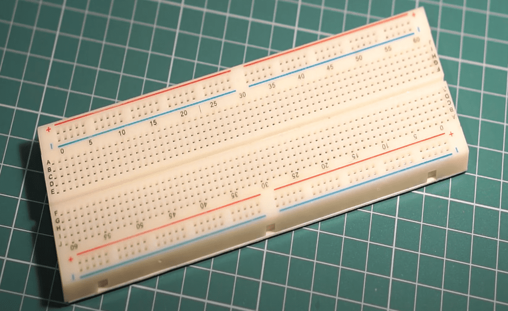
Quick prototyping makes use of breadboard boards, which primarily consist of plastic boards with interconnecting metals in grid form and three mounting holes. They come in various dimensions and have power grilles where power cables can be grounded. Disadvantages, on the other hand, include the fact that it requires no soldering, can be used repeatedly, is usually set up in an organized manner, and can be easy to make changes to circuits, making them suitable for learning purposes. However, breadboards introduce signal attenuation and more noise, provide inferior connections to soldered boards, and can accommodate medium current as well as most power sources.
2. Strip Boards (Vero Boards)
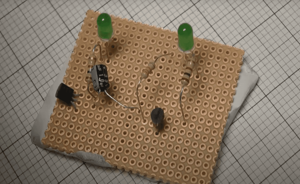
You can use stripboards, which are also known as Vero boards or perf boards, to create flat boards with parallel strips of conductive copper tracks soldered on them. They provide separate connections and customizable blocks of logic that are suitable for medium degrees of complexity. They require soldering. Contrary to strip board, track modification is difficult as it takes so much time and may not be the correct material of choice for high-density circuits or with small components because of the constrained space and the limit of the tracks.
3. Perf Board
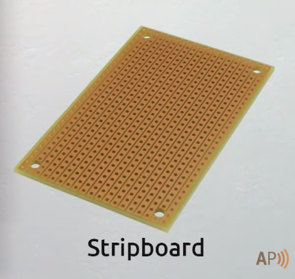
Perf board is the same board as stripboards, only that they have holes the same as the holes drilled for strips. These boards are for soldering components on them. They provide flexibility in circuit design and can be best used for rapid prototyping. Although the perf board boards are reusable and require some time to assemble, the possibilities are limited when it comes to high-density circuits since space constraints won’t permit it, and the use of soldering skills may prove to be a challenge for beginners or those who don’t have experience with soldering.
How to Use the Protoboard Effectively
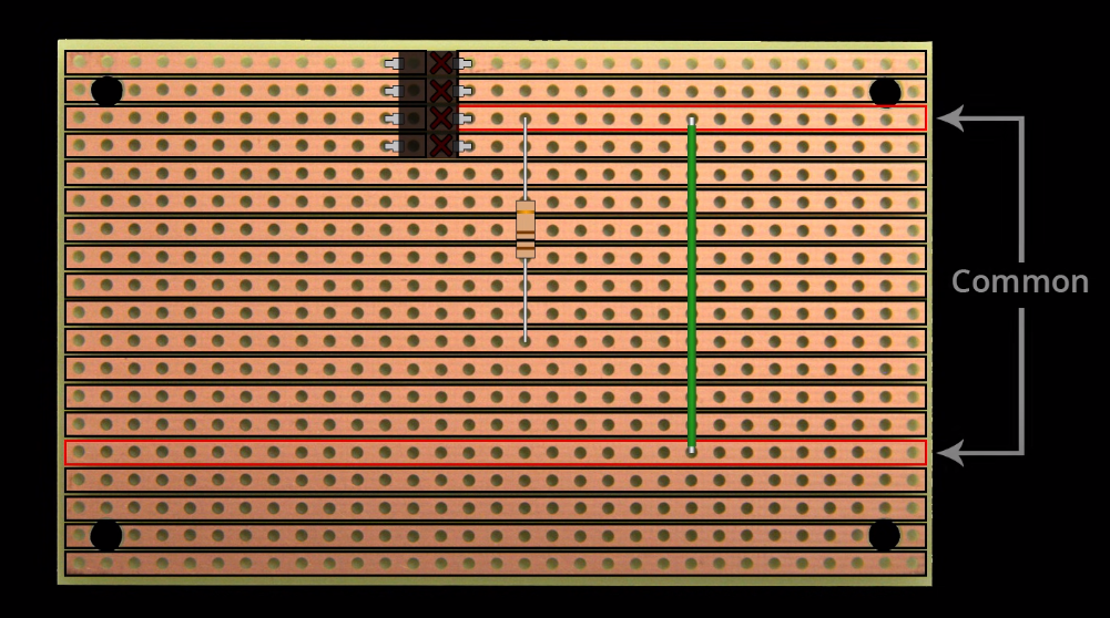
To use the protoboard effectively, here are the lists:
Plan Your Circuit
First, draw the circuit out on paper, use schematic software to draw the circuit on paper, or use schematic editor software before building it. As a result, the elements and their connections are visible in your mind with the aid of this process.
Select Components
Make sure you have all the electronics, such as resistors, capacitors, diodes, transistors, ICs, and connectors, before starting your circuit. Ensure there is compatibility with the positions of the air and electric tracks, along with the layout and spacing of solder components.
Prepare Components
Bend the leads of components if needed to fit the protoboard’s hole spacing from one side. Trim the excess leads to avoid short circuits or interference with adjacent electronics components.
Understand Protoboard Layout
Get a grip on the board as the solder and the holes travel through the lengthy copper rows of pins that interconnect. Normally, it has two parallel power and ground busses used for powering up and grounding the circuit.
Place Components
Installation of components onto the protoboard in accordance with the circuit scheme previously laid. Start with the main connections, such as power and ground, and then come to the other parts. placement of components as the rows and columns organize them so they make intuitive sense.
Make Connections
Participate in wiring encryption using jumper wires or component leads to connect the components. Necessary wire connections should be set out clearly while you avoid crossing the wires that are not crucial. Making use of the protoboard for the power and ground buses is very useful tool for
Test Continuity
Check the resistance between different points periodically using the multimeter tool to ensure continuity and proper connectivity. This will avoid having any broken spot or loops of unintentional links that can lead to problems later.
Test Your Circuit board
Once your circuit is fully assembled first place it on the protoboard, connect it to a power source and test its functionality. Check for expected behavior and troubleshoot any issues by inspecting connections and component placement.
Document your design
The display of your circuit design is important, and it involves component values, connections, and all traces of the changes to the to the temporary circuit, that were implemented in the prototyping.
Iterate and refine
Repeat your design after the tests and obtain the ratings of consumers. Improve and tune for high performance and minimal noise, and include custom extra items.
Electronic Components of the Prototyping Board
Knowledge of the electronic elements of prototyping boards is the first and most important prerequisite for anyone engaging in prototyping and circuit design. Skilfully navigating through terminal strips, power rails, jumper wires, resistors, capacitors, diodes, ICs, LEDs, switches, and potentiometers, designers will unfold their creativity and create electronic projects of all kinds on the versatile platform.
1. Terminal Strips
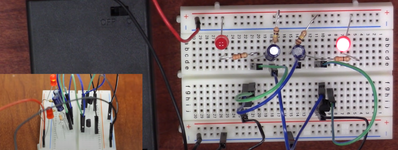
Terminal strips help in forming the skeleton of prototype boards. These are electromechanical components that have a set-up of strips and rods that are connected to each other. Copper traces are usually used for making these strips.
2. Power Rails
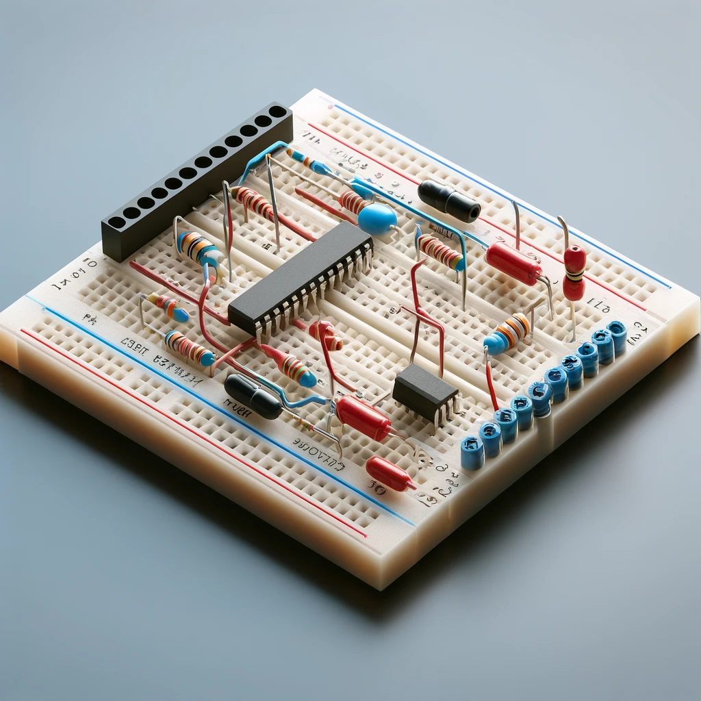
Prototyping boards and prototypes usually have power rails encircling their sides. The power tracks are designed to deliver voltage from the battery or power supply to the individual circuitry on board the prototype or board. They are often labeled as “+” (positive) and “-” (negative or ground), providing convenient access for connecting power sources and ground connections.
3. Jumper Wires
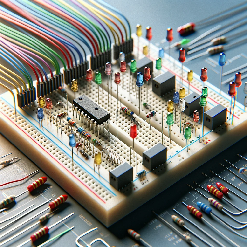
Jumper wires are made up of short wired pins or plugs attached to both ends and the middle of a wire. They are typically arranged in the medium to making an electrical connection between the component and terminal strip on the prototyping board.
4. Resistors
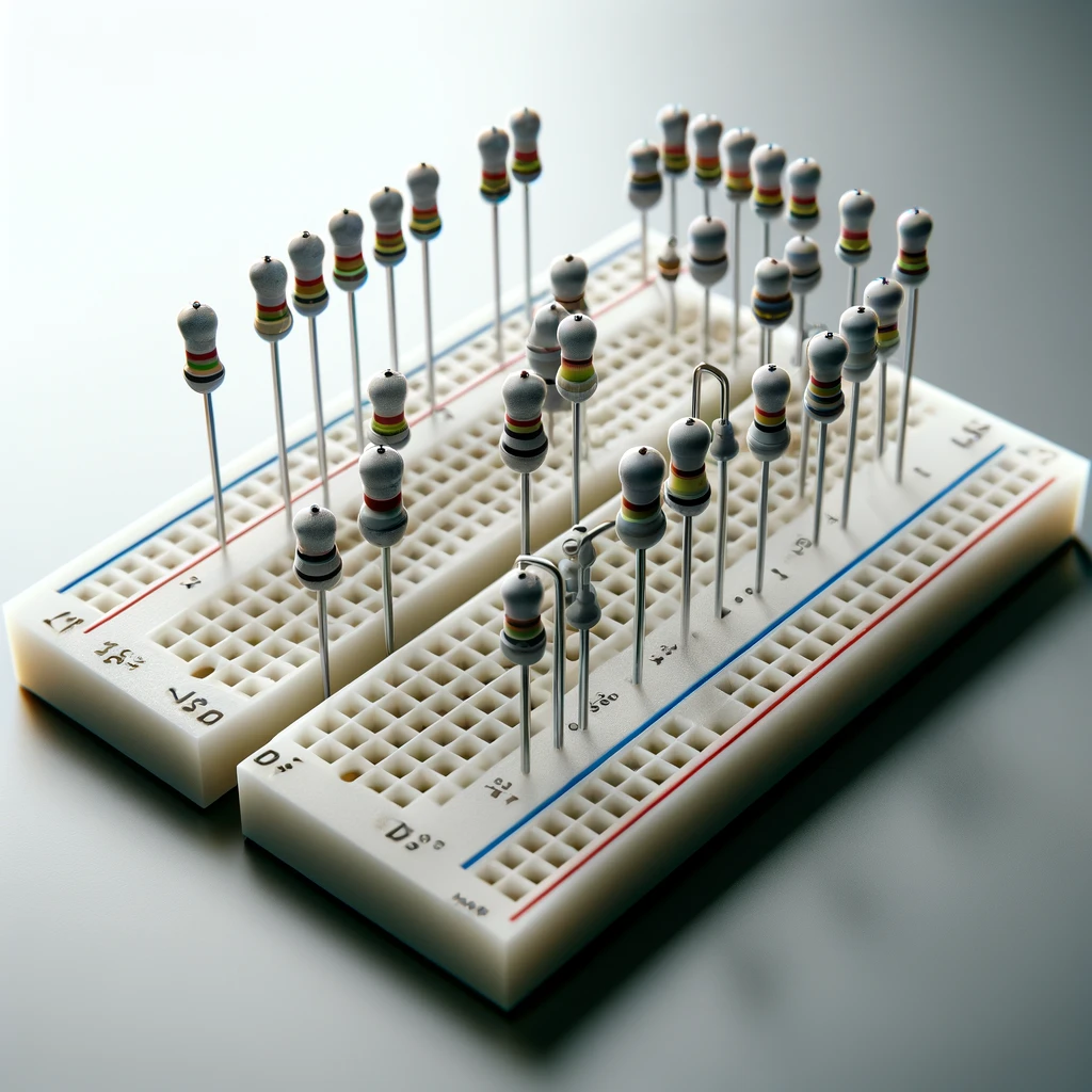
Resistors are non-active devices that limit the electric current flowing through a circuit. They are generally applied to regulate the voltage and current flow at different points in some simple circuits.
5. Capacitors
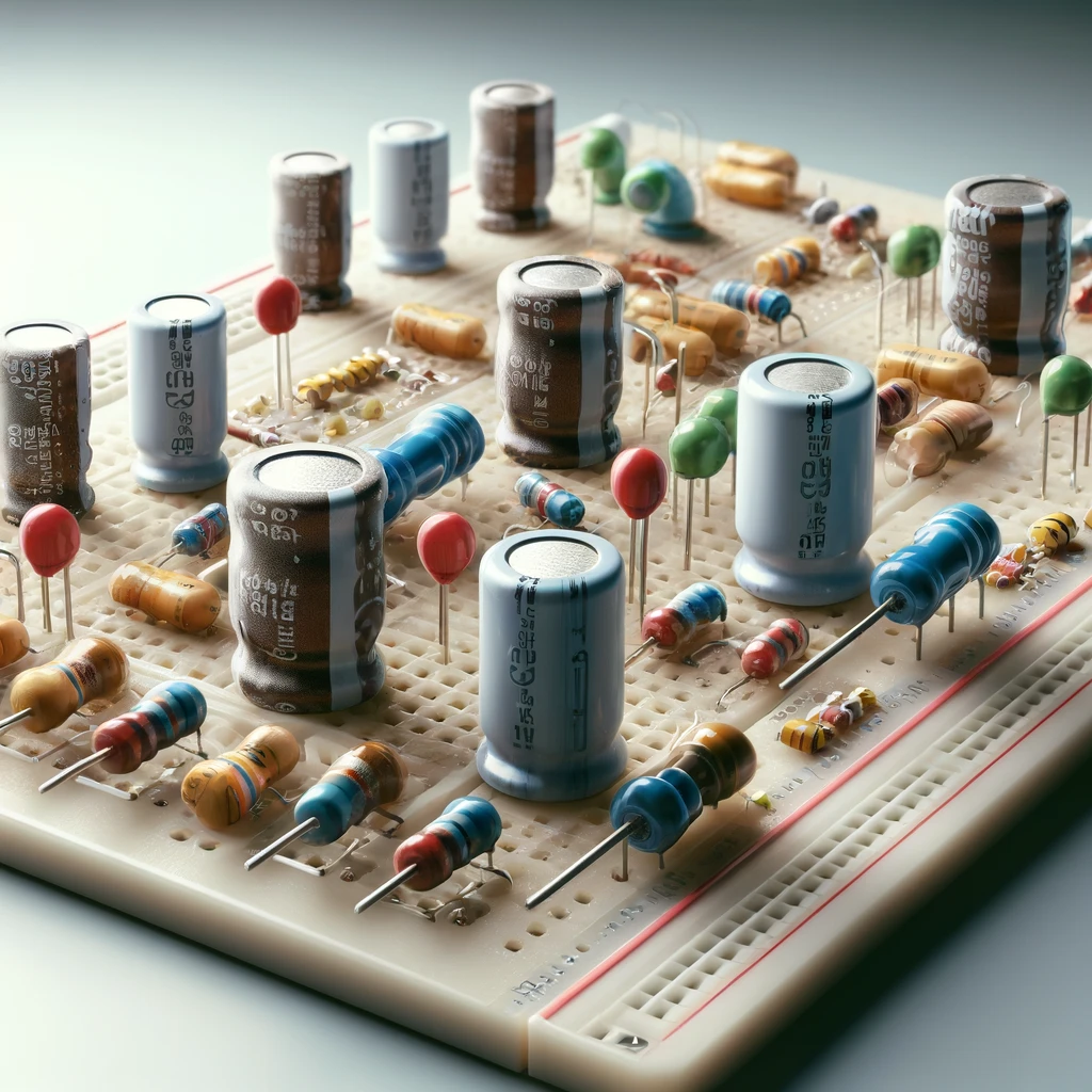
Capacitors have the capacity to store energy and release it in waves of electric charge. They play different roles in electronic circuits; for instance, they are used for ripple elimination, noise filtering, timing operations, and so forth.
6. Diodes
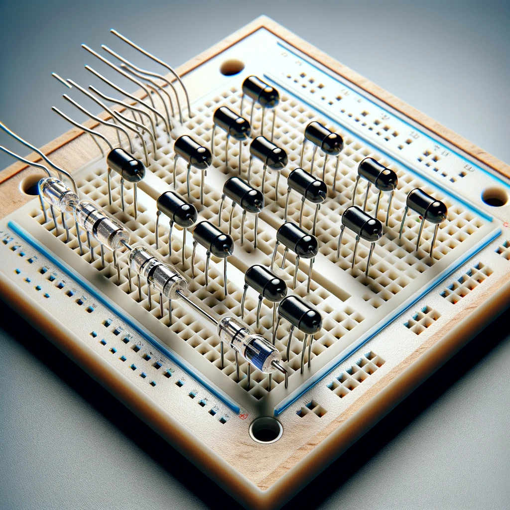
Diodes are semiconductor components that permit electricity to travel in one direction but impede it from going the other way. They are indispensable in getting AC into DC and in protecting circuits from reverse voltage.
7. Integrated Circuits (ICs)
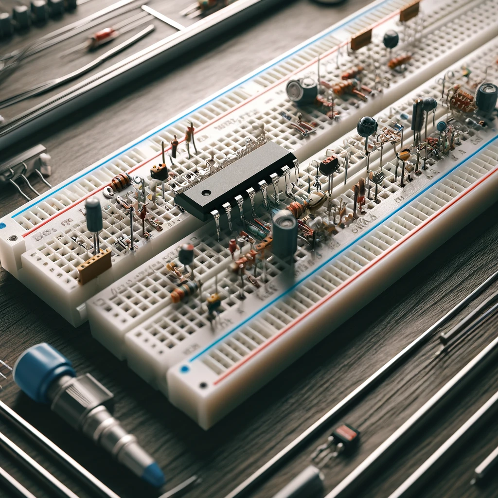
An IC is a complex semiconductor device that is capable of housing a large number of electronic elements, like transistors, resistors, and capacitors, within its chip. PCB prototyping boards usually include IC sockets or cut-out holes as places for ICs to be plugged, which enables the designers of electronic projects to develop complex electronic systems and microcontroller projects for testing purposes.
Steps in Constructing Electronic Circuits on Protoboards
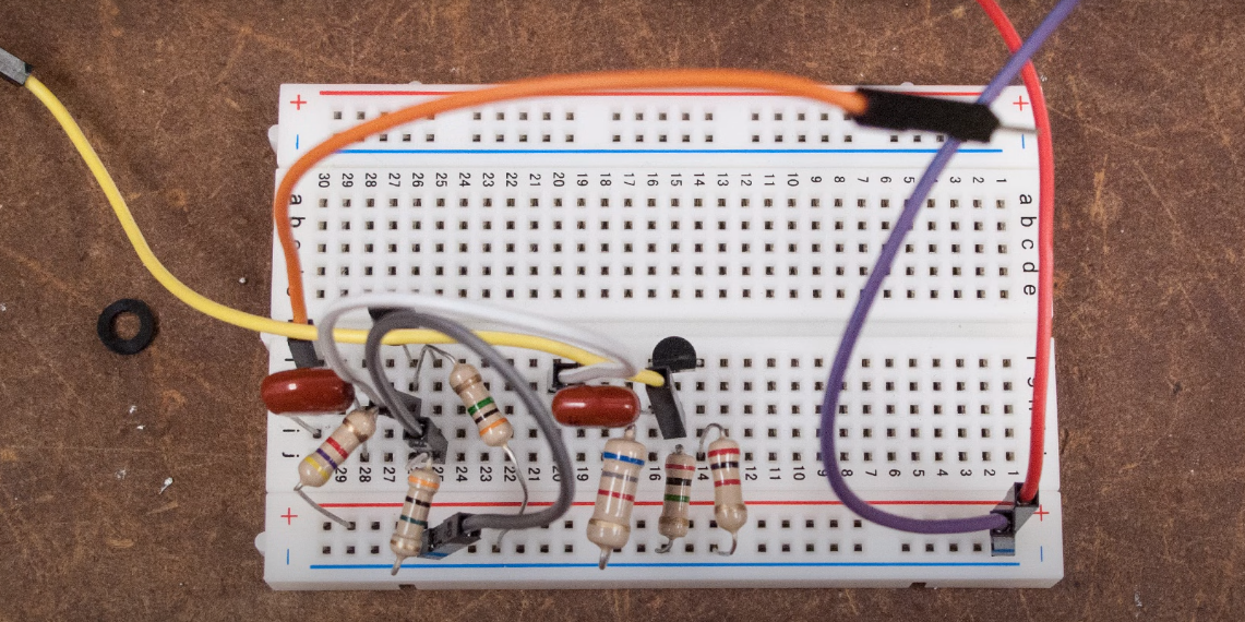
Here are the steps in constructing the electronic component circuit board on the protoboard:
1. Planning Your Circuit
You should always have an accurate plan before your circuit is built so that you won’t have a mess. This is representing what parts you’ll require, knowing the interconnections, and designing a schematic diagram if it is needed.
2. Component Placement
Begin by putting on the protoboard according to your circuit board design. For via holes that have many leads, like ICs and transistors, the components have to completely cross the middle of the gap between two terminal strips to have the correct connections.
3. Making Connections
Connect your components by plugging them using jumper wires or solid wires connected to the protoboard terminal and bus strips. Trim the wires at the proper length in order to avoid clutter and make the project set-up clean.
4. Power and ground
Link the power source, e.g., battery or DC power supply, into the bus lines on the protoboard. Verify that the power wires are firmly attached and that the polarities are correctly oriented. Connect all GND terminals of your devices to the bus bar.
5. Testing and troubleshooting:
By the time you have completed your circuit, it’s time to conduct a test. Turn on the power and put the multimeter or oscilloscope to work, checking voltages, currents, and signal waveforms. Direct yourself to be ready to do troubleshooting and make changes if the circuit does not operate in the expected manner.
Integrating Protoboard on Printed Circuit Boards
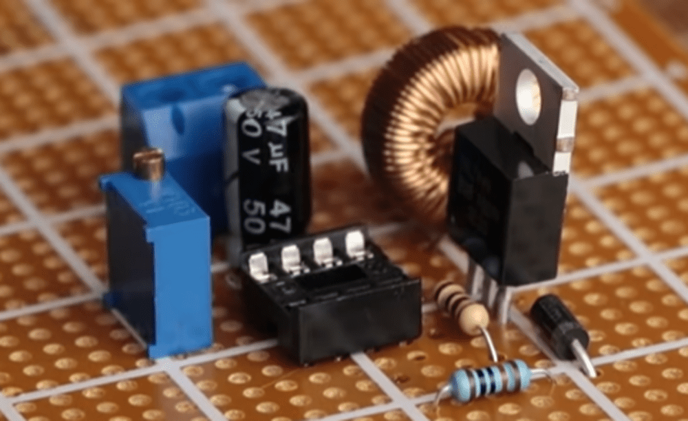
Integrating protoboards onto PCBs offers significant advantages in terms of reliability, scalability, and professional appearance. By following best practices and addressing potential challenges, engineers and designers can leverage the flexibility of protoboards during prototyping while ensuring a seamless transition to production-ready PCBs. This integration approach accelerates development cycles, improves design quality, and ultimately leads to more successful electronic products.
Conclusion
Protoboards are crucial tools in electronics prototyping, enabling quick assembly and testing of circuits without soldering. They offer advantages like rapid prototyping, reusability, and flexibility in design. Types include breadboards, strip boards, and perf boards. They include components like terminal strips, power rails, and resistors. Integrating protoboards onto PCBs offers reliability and scalability.
As you delve into your electronics hobbyist projects, consider integrating protoboards into your workflow. They facilitate experimentation, troubleshooting, and iteration, enabling you to refine your designs efficiently. Whether you’re a beginner or an experienced electronics hobbyists enthusiast, protoboards are a valuable asset in bringing your ideas to life. Explore the endless possibilities of protoboards in your electronics hobbyist journey and unlock new horizons of creativity and innovation!

